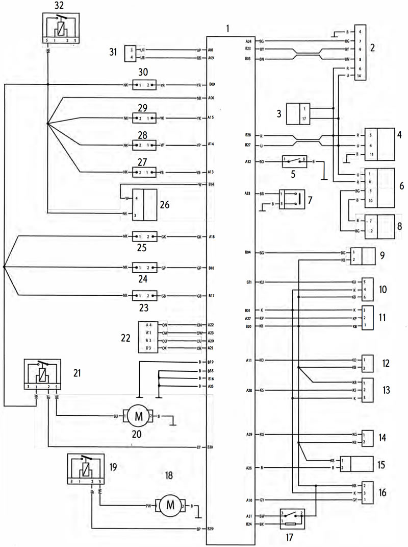
Key To Wiring Circuit Diagram
| Key | Item Description |
| 1 | Engine Control Module |
| 2 | Diagnostic Connector |
| 3 | ABS Modulator |
| 4 | Instrument Assembly |
| 5 | Clutch Switch |
| 6 | Immobiliser |
| 7 | Sidestand Switch |
| 8 | Ignition Switch |
| 9 | Fuel Level Sensor |
| 10 | Fall Detection Switch |
| 11 | Barometric Pressure Sensor |
| 12 | Intake Air Temperature Sensor |
| 13 | MAP Sensor |
| 14 | Coolant Temperature Sensor |
| 15 | Oxygen (Lambda) Sensor |
| 16 | Throttle Position Sensor |
| 17 | Gear Position Sensor |
| 18 | Fuel Pump |
| 19 | Fuel Pump Relay |
| 20 | Cooling Fan |
| 21 | Cooling Fan Relay |
| 22 | Idle Speed Control Stepper Motor |
| 23 | Coil 3 |
| 24 | Coil 2 |
| 25 | Coil 1 |
| 26 | Oxygen (Lambda) Sensor |
| 27 | Fuel Injector 3 |
| 28 | Fuel Injector 2 |
| 29 | Fuel Injector 1 |
| 30 | Purge Valve |
| 31 | Crankshaft Position Sensor |
| 32 | Engine Control Module Relay |
Key To Wiring Colour Codes
| Code | Wiring Colour |
| B | Black |
| U | Blue |
| N | Brown |
| G | Green |
| s | Slate/Grey |
| О | Orange |
| K | Pink |
| R | Red |
| P | Purple |
| W | White |
| V | Yellow |
| LG | Light Green |
| LU | Light Blue |
ECM Connector Pin Numbering
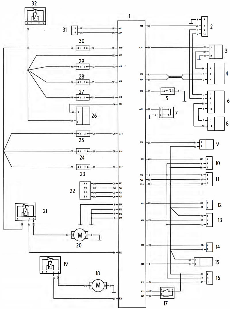
The above illustration shows the pin numbering system used in the engine management circuit diagram.
The black connector's pins are prefixed A and the grey connector's pins B. As viewed from the mating face with the ECM (as per the illustration) pins are numbered from right to left with number one in the top right corner.