
Note:
- A major cause of hidden electrical faults can be traced to faulty electrical connectors. For example:
- Dirty/corroded terminals.
- Damp terminals.
- Broken or bent cable pins within multi-plugs.
For example, the electronic control module (ECM) relies on the supply of accurate information to enable it to plan the correct fueling and ignition timing. One dirty terminal will cause an excessive voltage drop resulting in an incorrect signal to the ECM.
If, when carrying out fault diagnosis, a fault appears to clear by simply disconnecting and reconnecting an electrical plug, examine each disconnected plug for the following.
Before Disconnection:
- If testing with a voltmeter, the voltage across a connector should be virtually battery volts (unless a resistor is fitted in the circuit). If there is a noticeable change, suspect faulty/dirty connections.
When Disconnecting a Connector:
- Check for a security device that must be released before the connector can be separated. E.G. barb, hook and eye etc.
When Inspecting a Connector:
- Check that the individual pins have not been bent.
- Check for dampness/dirt/corrosion.
- Check cables for security.
- Check cable pin joints for damage.
When Connecting a Connector:
- Ensure there is no dirt around the connector/seal.
- Push together squarely to ensure terminals are not bent or incorrectly located.
- Push the two halves together positively.
Disconnection of ECM connectors
Note: Two different coloured and shaped connectors are used in the ECM, which ensures correct connection is always made. The connectors on the ECM are coloured black and grey, and correspond with identical coloured connectors on the main harness.
Caution: When disconnecting a connector, never pull directly on the wires as this may result in cable and connector damage.
Caution: Never disconnect the ECM when the ignition switch is in the 'ON' position as this may cause multiple fault codes to be logged in the ECM memory.
Always disconnect an ECM after disconnecting the battery negative (black) lead first.
1. Turn the ignition to the 'OFF' position and wait at least 1 minute for the ECM to complete its power down sequence.
2. Press down on the locking device and gently pull back on the connector to release it from the ECM.
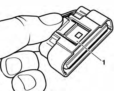
1. Locking device
Note: The ECM is located beneath the rider's seat, to the left of the battery.
Reconnection of ECM connectors
Note: Two different coloured and shaped connectors are used in the ECM, which ensures correct connection is always made. The connectors on the ECM are coloured black and grey, and correspond with identical coloured . connectors on the main harness.
Caution: Damage to the connector pins may result if an attempt to fit the connectors incorrectly is made.
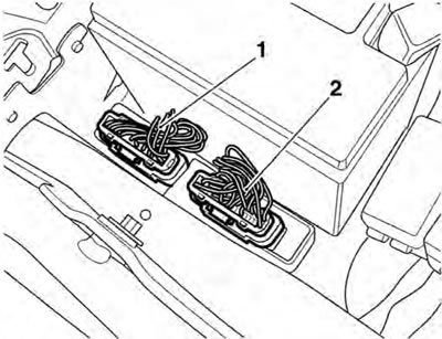
1. ECM grey connector; 2. ECM black connector
1. Fit the first connector into its socket and, whilst holding the connector in place, insert it fully into the ECM until the locking device retains it.
2. Repeat the above for the second connector.
Further Diagnosis
The tables that follow will, if used correctly, help to pinpoint a fault in the system once a diagnostic trouble code has been stored.