

Engine starting and ignition are inhibited when the stand is down and/or a gear is engaged.
Troubleshooting
Check the condition of the 15 A fuses.
Check the neutral light switch.
Check the stand switch.
Check the diode.
Check the starter relay; see 8.6.1.
Fit a substitute CDI unit known to be operating correctly.
Test readings
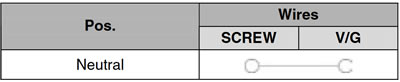
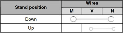
Check for continuity across the contacts using a multimeter set to the ohm range. Refer to the diagrams below.
Neutral light switch test
Stand test
Diode test
To test diode operation: Disconnect the two-way connector (1) (coloured white).
Warning! Make sure to refit the connector (1) to the matching connector on assembly

Place a multimeter in the diode-test mode and measure across the two male terminals accommodated inside the diode as shown in the diagram.
Correct reading (layout A): 0-1 Ω.
Correct reading (layout B): ∞.
If your multimeter does not include a diode-test feature, feed 12 Volts to the diode, fit a 12 V - 2 W bulb to the positive lead and connect the leads to the diode as shown in the diagram.

Warning! Do not use a bulb rated higher than 2 W or the diode will damage.
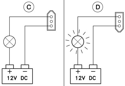
Test (C): the bulb stays off.
Test (D): the bulb comes on.