The system consists of three different circuits:
- Fuel circuit
- Air intake circuit
- Electrical circuit (with control unit, sensors and actuators).
Importance of the air-fuel mixture and the ignition advance
Correct management of the air-fuel ratio and the ignition advance are fundamental requirements for optimal engine operation.
The air-fuel mixture is given by the ratio, in weight, of air to fuel taken in by the engine: the ideal or stoichiometric ratio is that which determines complete combustion. Excessive or insufficient air give rise to, respectively, a lean (or weak) mixture or a rich mixture, which affect power and consumption, as well as emissions of exhaust gases.
Electronic control of ignition timing advance makes it possible to optimise the performance of the engine, maximum power output, fuel consumption and the concentration of exhaust pollutants.
Electronic ignition timing control combined with fuel supply control allows for optimal engine operation in all conditions of use (low temperature start, warm-up stage, transitory acceleration/deceleration stages, engine under partial load, full load, idle).


Siemens M3C fuel injection-ignition system
The Marelli injection-ignition system is the Alfa/N type, in which the engine speed and throttle position are used as the main parameters for measuring the quantity of intake air. If the quantity of air is known, the quantity of fuel can be dosed accordingly to obtain the required ratio. Additional sensors in the system (engine rpm, aspirated air pressure, air temperature, engine oil temperature and lambda sensor to control CO level) are used to adjust the basic engine control strategy in accordance with the operating conditions. The engine speed and the throttle angle are also used to calculate the optimal ignition advance for all operating conditions. The quantity of air taken in by each cylinder during each cycle depends on the density of the air in the intake manifold, the cylinder capacity and the volumetric efficiency.
The volumetric efficiency of the engine is determined experimentally throughout the entire range of operating conditions (rotation speed and engine load conditions). The values obtained in this way are then used for the generation of a map which is stored in the Flash EPROM of the Siemens M3C ECU for injection control. The Flash Eprom can be programmed via CAN line. Fuel injection control is of the phased sequential type, i.e. the injectors are not operated in parallel. Fuel delivery to each cylinder may start during the expansion stroke and may extend up to after the beginning of the induction stroke. Fuel cut-off timing (the time when the injectors are closed), is saved onto a special map, which is stored in the ECU Flash Eprom. Ignition is of the static inductive discharge type, featuring dwell time control so as to ensure coil charging at steady power Power modules for coil power supply are included in the ECU hardware. Advance curves are stored in the ECU Flash Eprom. Both coils and power modules are controlled by the ECU, which calculates the ignition advance.
Note: To test the components and wiring of the injection - ignition system, use the "DDS" tester, following the indications given in the paragraph "Guided diagnosis".
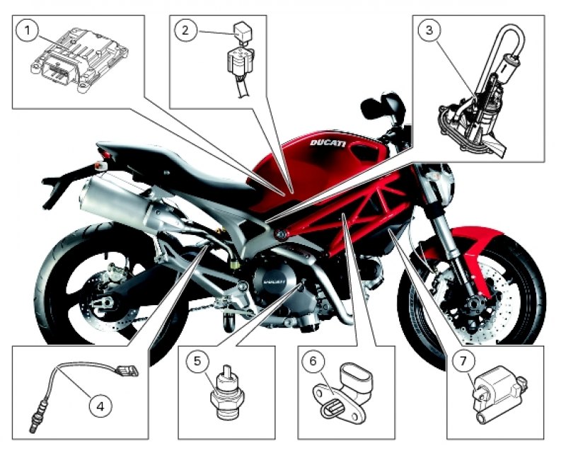
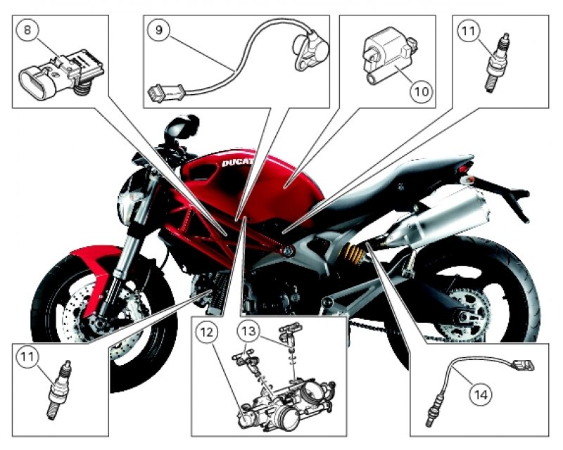
Key to the sensor position diagram
- 1. Injection ECU
- 2. Injection relay
- 3. Fuel pump
- 4. Lambda sensor (horizontal cylinder)
- 5. Engine temperature sensor
- 6. Air temperature sensor
- 7. Horizontal cylinder coil
- 8. Pressure sensor
- 9. Engine speed sensor
- 10. Vertical cylinder coil
- 11. Spark plug
- 12. Throttle position sensor
- 13. Injectors
- 14. Lambda sensor (vertical cylinder)