Oxygen Sensor Heater Inspection
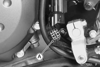
- Disconnect the oxygen sensor lead connector [A]

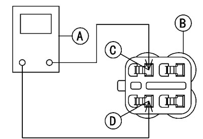
- Set the hand tester [A] to the x 1 Q range and connect it to the terminals in the oxygen sensor lead connector [B].
- Black [C]
- Black [D]
Special Tool - Hand Tester: 57001-1394
Oxygen Sensor Heater Resistance
Standard: 11.7-14.5 Q at 20°C (68°F)
If the tester reading is not as specified, replace the oxygen sensor with a new one.

If the tester reading is specified, check the power source voltage Inspection.
Note: Be sure the battery is fully charged.
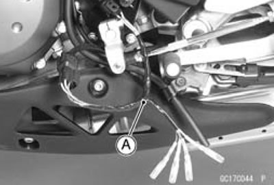
- Disconnect the oxygen sensor connector and connect the harness adapter [A] between these connectors.
Special Tool - Oxygen Sensor Measuring Adapter: 57001 -1682
- Connect a digital meter to the to the harness adapter lead.

Oxygen Sensor Power Source Voltage
Connections to Adapter
- Tester (+) → W/Y (sensor BK) lead
- Tester (-) → Battery (-) Terminal
- Measure the power source voltage with the engine stopped, and with the connector joined.
- Turn the ignition switch ON.
Power Source Voltage at Sensor
Standard: Battery Voltage
- Turn the ignition switch OFF.
If the reading is incorrect, check the following.
- Battery
- Main Fuse 30 A
- Oxygen Sensor Heater Fuse 10 A
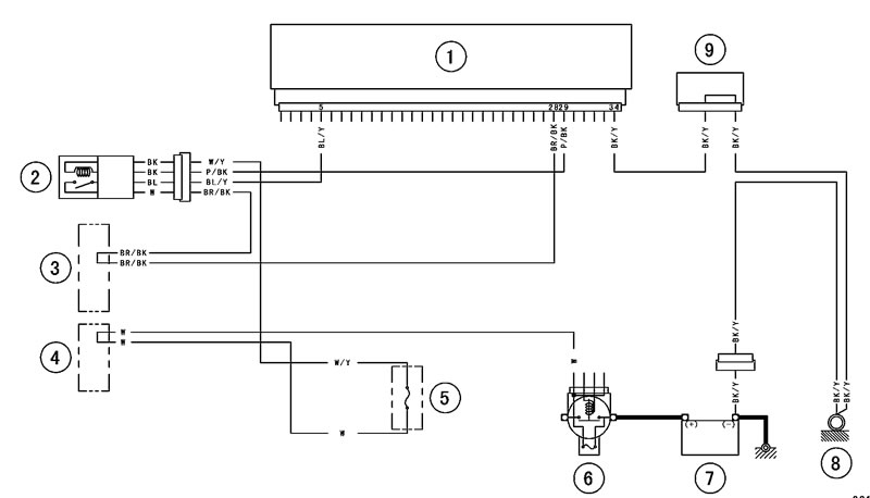
If the reading is good, the power source voltage is normal, Inspect the Pink/Black lead between the oxygen sensor connector and the ECU for continuity, using the following diagram.
If the wiring is good, inspect the ECU for its ground, and power supply (See ECU Power Supply Inspection).
If the ground and power supply are good, replace the ECU (See ECU Removal/Installation).
Oxygen Sensor Circuit

1. ECU; 2. Oxygen Sensor; 3. Water-proof Joint E; 4. Water-proof Joint C; 5. Oxygen Sensor Heater Fuse 10 A; 6. Main Fuse 30 A; 7. Battery; 8. Frame Ground; 9. Joint Connector
