Note: Valve clearance must be checked and adjusted when the engine is cold (room temperature).
Remove:
- Cylinder Head Cover (See Cylinder Head Cover Removal in the Engine Top End chapter)
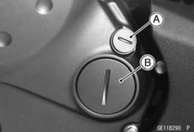
- Timing Inspection Cap [A]
- Timing Rotor Bolt Cap [B]

- Check the valve clearance when the pistons are at TDC.
- The pistons are numbered beginning with the engine left side.
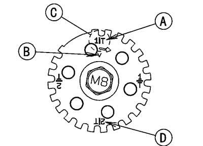
- Using a wrench on the timing rotor bolt, turn the crankshaft clockwise until the 1/T mark line [A] on the timing rotor is aligned with the notch [B] in the edge of the timing inspection hole [C] in the clutch cover for #1 piston and 2/T mark line [D] for #2 piston.

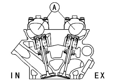
Measure the valve clearance of the valves for which the cams [A] are turned away from each other.

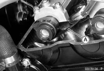
- Using the thickness gauge [A], measure the valve clearance between cam and valve lifter.
Valve Clearance
Standard:
- Exhaust 0.22-0.31 mm (0.0087-0.0122 in.)
- Inlet 0.15-0.21 mm (0.0059-0.0083 in.)
Each piston has two inlet and two exhaust valves. Measure these two inlet or exhaust valves at the same crankshaft position.
Note: Check the valve clearance using this method only. Checking the clearance at any other cam position may result in improper valve clearance.
Valve Clearance Measuring Position
#1 Piston TDC at End of Compression Stroke:
- Inlet valve clearances of#1 piston, and Exhaust valve clearances of #1 piston
#2 Piston TDC at End of Compression Stroke:
- Inlet valve clearances of#2 piston, and Exhaust valve clearances of #2 piston
If the valve clearance is not with in the specified range, first record the clearance, and adjust it.

