Note: The fuel cut-off circuit is incorporated in this ECM in order to prevent over-running of engine. When engine speed reaches 7 200 r/min, this circuit cuts off fuel at the fuel injector. But under no load, the clutch lever is pulled or the gear position is neutral, this circuit cuts off fuel when engine speed reaches 7 100 r/min.
Caution: Under no load, the engine can run over 7 100 r/min though the fuel cut-off circuit is effective, which may possibly cause engine damage. Do not run the engine without load over 7 100 r/min at anytime.
Troubleshooting
No spark or poor spark
Note: Check that the transmission is in neutral and the engine stop switch is in the "RUN" position. Grasp the clutch lever. Check that the fuse is not blown and the battery is fully-charged before diagnosing.
Step 1
- 1) Check the ignition system couplers for poor connections.
Is there connection in the ignition system couplers?
| YES | Go to Step 2. |
| NO | Poor connection of couplers |
Step 2
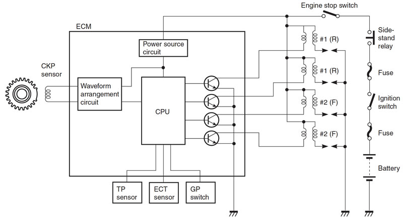
- 1) Measure the battery voltage between input lead wires at the ECM with the ignition switch in the "ON" position. (E-02, 19, 24: O/G and B/W, E-03, 28, 33: O/W and B/W)
Is the voltage OK?
| YES | Go to Step 3. |
| NO | Faulty ignition switch Faulty turn signal/side-stand relay Faulty engine stop switch Broken wire harness or poor connection of related circuit couplers |
Step 3
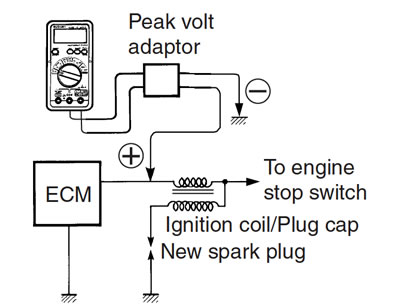
- 1) Measure the ignition coil primary peak voltage.
Note: This inspection method is applicable only with the multi-circuit tester and the peak volt adaptor.
Is the peak voltage OK?
| YES | Go to Step 4. |
| NO | Go to Step 5. |
Step 4
- 1) Inspect the spark plugs. (2-13)
Is the spark plug OK?
| YES | Go to Step 5. |
| NO | Faulty spark plug(-s). |
Step 5
- 1) Inspect the ignition coil/plug caps and ignition coils.
Is the ignition coil/plug cap and ignition coils OK?
| YES | Go to Step 6. |
| NO | Poor connection of the ignition coil/plug cap(-s) and ignition coils. Faulty ignition coil/plug cap(-s) and ignition coils. |
Step 6
- 1) Measure the crankshaft position sensor peak voltage and its resistance.
Note: The crankshaft position sensor peak voltage inspection is applicable only with the multi-circuit tester and peak volt adaptor.
Is the peak voltage and resistance OK?
| YES | Faulty ECM Open or short circuit in wire harness Poor connection of ignition couplers |
| NO | Faulty CKP sensor Metal particles or foreign material being stuck on the CKP sensor and rotor tip |
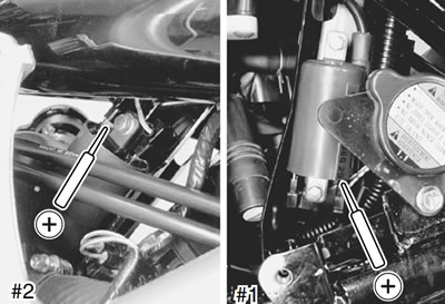
Inspection ignition coil primary peak voltage
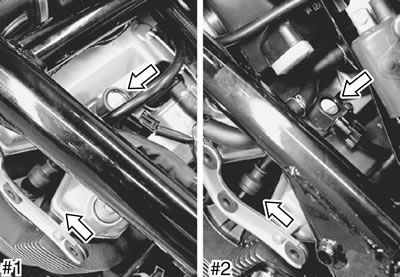
- Remove the left frame side covers. (9-5)
- Remove the fuel tank. (6-3)
- Remove the frame head covers and right radiator covers. (9-6)
- Remove the front cylinder right head cover cap and rear cylinder left head cover cap. (2-13)
- Disconnect all the ignition coil/plug cap lead wire couplers before removing the ignition coil/plug caps.
- Remove the ignition coil/plug caps and disconnect the plug caps.
Caution:
- Do not remove the ignition coil/plug cap before disconnecting the lead wire coupler, or the lead wire will be damaged.
- Do not pry up the ignition coil/plug cap with a screwdriver or a bar to avoid damage.
- Be careful not to drop the ignition coil/plug cap as it may open or short in a circuit.
- Connect the new spark plugs to each ignition coil/plug caps and plug caps.
- Connect all the ignition coil/plug cap lead wire couplers to the ignition coil/plug caps respectively, and ground them on the cylinder head (each spark plug hole).
- Connect new spark plugs to each spark plug cap and ground them to the cylinder head.
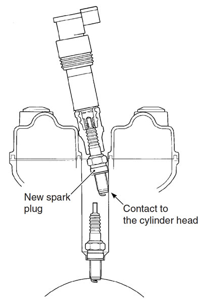
Note: Be sure that all couplers and spark plugs are connected properly and the battery used is in fully-charged condition.
Ignition coil/plug cap primary peak voltage
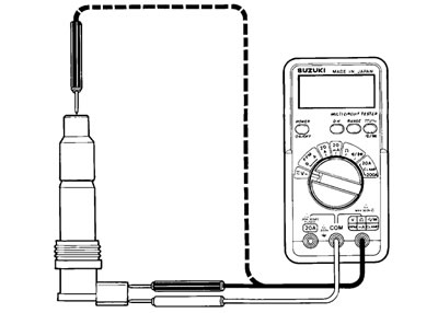
- Inspect each ignition coil primary peak voltage at the ignition coil/plug cap coupler.
- Connect the multi-circuit tester with peak voltage adaptor as follows.
#1 ignition coil/plug cap:
- W/Bl wire terminal (+ Probe) - Ground (− Probe) terminal
#2 ignition coil/plug cap:
- Black wire terminal (+ Probe) - Ground (− Probe) terminal
- 09900-25008: Multi-circuit tester set
- 09900-25009: Needle pointed probe set
Caution: Before using the multi-circuit tester and peak volt adaptor, be sure to refer to the appropriate instruction manual.
Note: Use the special tool, to prevent the rubber of the water proof coupler from damage.
- Shift the transmission into neutral and turn ignition switch "ON".
- Pull the clutch lever.
- Crank the engine a few seconds with the starter motor by depressing starter button and check the ignition coil primary peak voltage.
- Repeat the above inspection a few times and measure the highest peak voltage.
- Tester knob indication: Voltage
- Ignition coil/plug cap primary peak voltage: 80 V and more
Warning: Do not touch the tester probes and spark plugs to prevent an electric shock while testing. If the peak voltage is lower than the standard range, check the ignition coil/plug cap.
Ignition coil primary peak voltage
- Inspect each ignition coil primary peak voltage in the following procedure.
- Connect the multi-circuit tester with peak voltage adaptor as follows.
- #1 ignition coil: + Probe: Yellow lead wire terminal − Probe: Ground
- #2 ignition coil: + Probe: Green lead wire terminal − Probe: Ground
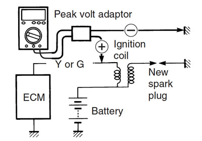
Note: Do not disconnect the ignition coil primary wire coupler.
- 09900-25008: Multi-circuit tester set
Caution: Before using the multi-circuit tester and peak volt adaptor, be sure to refer to the appropriate instruction manual.
- Inspect the ignition coil primary peak voltage in the same manner as the ignition coil/plug cap.
- Tester knob indication: Voltage
- Ignition coil primary peak voltage: 250 V and more
If the peak voltage is lower than the specified values, inspect the ignition coil.
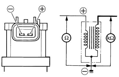
Ignition coil/plug cap resistance
- Disconnect the ignition coil/plug cap.
- Check the ignition coil/plug cap for resistance in both primary and secondary coils. If the resistance is not within the standard range, replace the ignition coil/plug cap with a new one.
- 09900-25008: Multi-circuit tester set
- Tester knob indication: Resistance (Ω)
Ignition coil/plug cap resistance:
- Primary : 1.1 - 1.9 Ω (+ tap - − tap)
- Secondary: 10.8 - 16.2 kΩ (Plug cap - − tap)
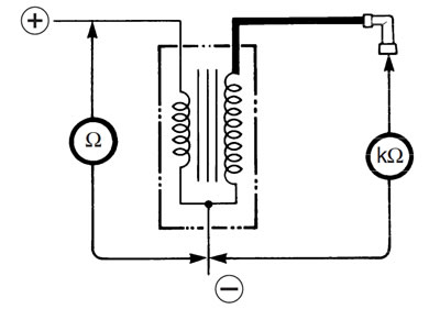
Ignition coil resistance
- Disconnect the spark plug caps.
- Measure the ignition coil resistance in both the primary and secondary windings. If the resistance is not within the standard range, replace the ignition coil with a new one.
- 09900-25008: Multi-circuit tester set
- Tester knob indication: Resistance (Ω)
Ignition coil resistance:
- Primary: 1.8 - 3.0 Ω (+ terminal - − terminal)
- Secondary: 16 - 26 kΩ (Plug cap - − terminal)
CKP Sensor peak voltage
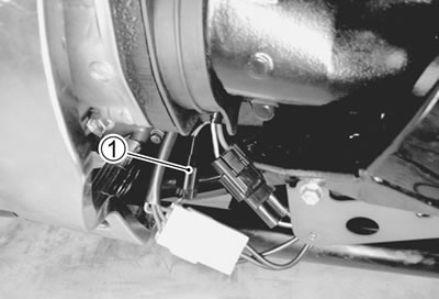
- Remove the fuel tank. (6-3)
- Remove the left frame side cover. (9-5)
- Remove the left frame lower side cover. (3-6)
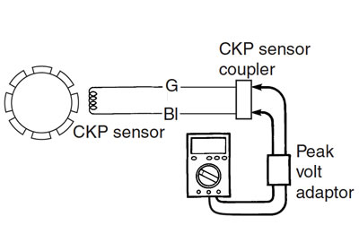
- Disconnect the CKP sensor lead wire coupler 1 and connect the multi-circuit tester with the peak volt adaptor.
- Blue (+ Probe) - Green (− Probe)
- Measure the CKP sensor peak voltage at the CKP sensor lead wire coupler.
Caution: Before using the multi-circuit tester and peak volt adaptor, be sure to refer to the appropriate instruction manual.
- Shift the transmission into the neutral and turn ignition switch "ON".
- Crank the engine a few seconds with the starter motor by depressing starter button and check the CKP sensor peak voltage.
- Repeat the above test procedure a few times and measure the highest peak voltage.
- Tester knob indication: Voltage
- 09900-25008: Multi-circuit tester set
- CKP sensor peak voltage: 1.5 V and more
If the peak voltage is within the specification, check the continuity between the CKP sensor coupler and ECM coupler.
Caution: Normally, use the needle pointed probe to the backside of the lead wire coupler to prevent the terminal bend and terminal alignment.
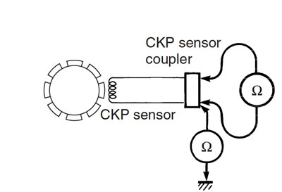
CKP Sensor resistance
- Measure the resistance between the lead wires and ground. If the resistance is not within the standard range, replace the CKP sensor with a new one.
- 09900-25008: Multi-circuit tester set
- Tester knob indication: Resistance (Ω)
- CKP sensor resistance: 190 - 290 Ω (Green - Blue)
- ∞ Ω (Green - Ground)