
ABS warning light on (no dtcs stored)
| Fault Code | Possible cause | Action |
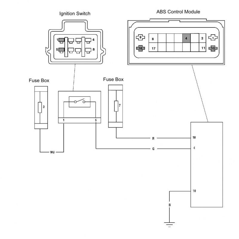
| ABS Warning Light ON (No DTCs Stored) | ABS Ignition supply fuse/circuit fault | Ensure ABS ECM connector is secure. Disconnect ABS ECM connector and proceed to pinpoint test 1: |
| ABS Warning light circuit fault | Refer to CAN Fault. |
Pinpoint tests
| Test | Result | Action | |
| 1 | Check cable and terminal integrity: - ABS ECM connector pin 4 and ground pin 10 | OK | Proceed to test 2 |
| Faulty | Rectify fault, proceed to test 3 | ||
| 2 | Check cable continuity of the ABS ignition supply circuit: With the ignition 'ON', check voltage between: - ABS ECM connector pin 4 and ground pin 10 | Voltage greater than 10 V | Proceed to test 3 |
| Voltage less than 10 V | Locate and rectify wiring fault, proceed to test 3 | ||
| 3 | Reconnect ABS ECM harness, clear fault code and test ABS to verify fault cleared. | OK | Action complete - quit test |
| Fault still present | Contact Triumph service | ||
Circuit diagram

ABS warning light does not illuminate (no dtcs stored)
| Fault Code | Possible cause | Action |
| ABS Warning Light OFF (No DTCs Stored) | ABS ECM ground circuit fault | Ensure ABS ECM connector is secure. Ensure ABS ECM ground connection is secure. Disconnect ABS ECM connector and proceed to pinpoint test 1: |
| Warning light circuit fault | Refer to CAN Fault |
Pinpoint tests
| Test | Result | Action | |
| 1 | Check the ABS warning light circuit and ignition fuses - fuse 3 and fuse 7 | OK | Proceed to test 2 |
| Faulty | Rectify fault, proceed to test 5 | ||
| 2 | Check cable and terminal integrity: - ABS ECM connector pin 4 and ground pin 10 | OK | Proceed to test 3 |
| Faulty | Replace fuse, proceed to test 5 | ||
| 3 | Check cable for short to voltage: With ignition 'OFF', check voltage between: - ABS ECM connector pin 4 and ground | 0 V | Proceed to test 4 |
| Above 3 V | Locate and rectify wiring fault, proceed to test 5 | ||
| 4 | Check cable for continuity: ABS ECM connector pin 10 and ground: | OK | Proceed to test 5 |
| Faulty | Locate and rectify fault, proceed to test 5 | ||
| 5 | Reconnect ABS ECM harness, clear fault code and test ABS to verify fault cleared. | OK | Action complete - quit test |
| Fault still present | Contact Triumph service | ||
Circuit diagram

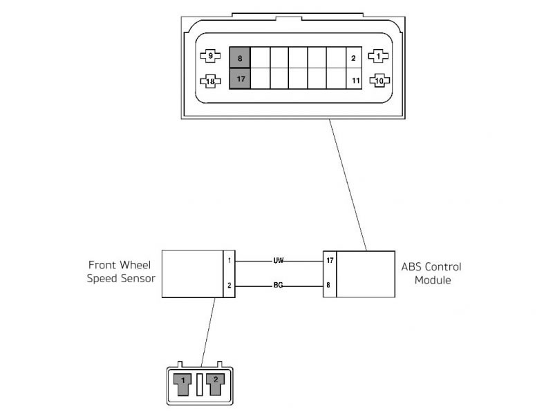
Front wheel sensor open circuit/short circuit
| Fault Code | Possible cause | Action |
| C1611 | Front wheel sensor short circuit to ground or open circuit | Ensure ABS ECM connector is secure. Ensure wheel speed sensor connector is secure. Disconnect ABS ECM connector and proceed to pinpoint test 1: |
Pinpoint tests
| Test | Result | Action | |
| 1 | Check cable and terminal integrity: - ABS ECM connector pin 17 and ABS ECM connector pin 8 | OK | Proceed to test 2 |
| Faulty | Rectify fault, proceed to test 9 | ||
| 2 | Check cable for short circuit: - ABS ECM connector pin 8 and ground | OK | Proceed to test 4 |
| Short circuit | Proceed to test 3 | ||
| 3 | Disconnect the front wheel speed sensor connector. Check cable for short circuit: - Wheel speed sensor connector pin 2 (motorcycle harness side) and ground | OK | Replace the wheel speed sensor, proceed to test 9 |
| Short circuit | Locate and rectify wiring harness fault, proceed to test 9 | ||
| 4 | Check cable for short circuit: - ABS ECM connector pin 17 and ground | OK | Proceed to test 6 |
| Short circuit | Proceed to test 5 | ||
| 5 | Check cable for short circuit: - Wheel speed sensor connector pin 1 (motorcycle harness side) and ground | OK | Replace the wheel speed sensor, proceed to test 9 |
| Short circuit | Locate and rectify wiring harness fault, proceed to test 9 | ||
| 6 | Check cable continuity: - ABS ECM connector pin 8 and wheel speed sensor connector pin 2 (motorcycle harness side) | OK | Proceed to test 7 |
| Open circuit | Locate and rectify wiring harness fault, proceed to test 9 | ||
| 7 | Check cable continuity: - ABS ECM connector pin 17 and wheel speed sensor connector pin 1 (motorcycle harness side) | OK | Proceed to test 8 |
| Open circuit | Locate and rectify wiring harness fault, proceed to test 9 | ||
| 8 | Reconnect the front wheel speed sensor connector. Check the wheel speed sensor operation: - Connect a suitable voltage supply between 10 V and 16 V between ABS ECM connector pin 8 (positive) and pin 17 (negative), and measure the current consumption of the wheel speed sensor | 1.8 mA to 16.8 mA | Proceed to test 9 |
| Faulty | Replace the wheel speed sensor, proceed to test 9 | ||
| 9 | Reconnect ABS ECM harness, clear fault code and test ABS to verify fault cleared. | OK | Action complete - quit test |
| Fault still present | Contact Triumph service | ||
Circuit diagram
Wheel speed sensor current consumption data under typical conditions:
| Supply Voltage | Min | Typical | Max |
| 10 - 16 V | 1.8 mA | 7.5 mA | 16.8 mA |
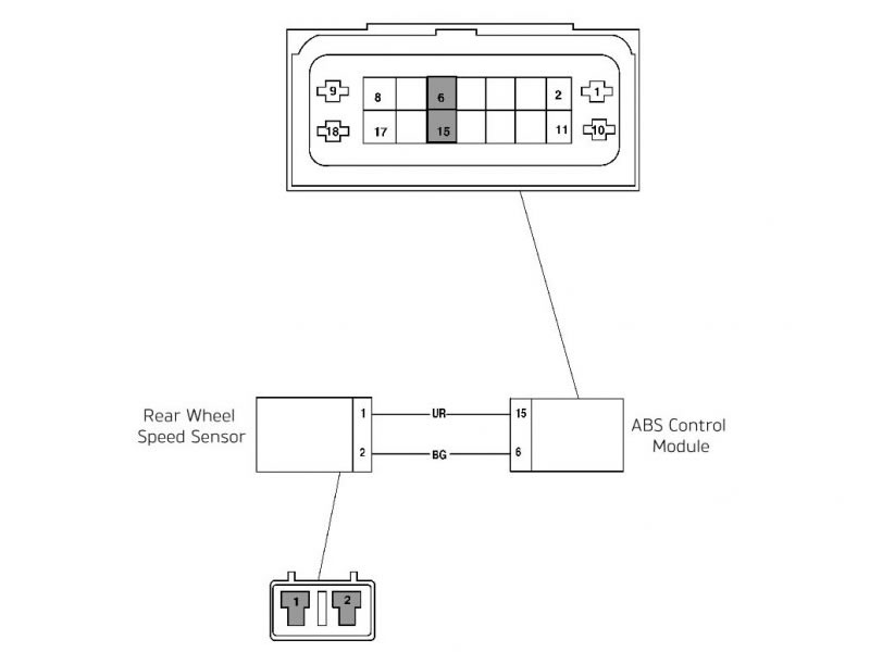
Rear wheel sensor open circuit/short circuit
| Fault Code | Possible cause | Action |
| C1613 | Rear wheel sensor short circuit to ground or open circuit | Ensure ABS modulator/ECM connector is secure. Ensure wheel speed sensor connector is secure. Disconnect ABS modulator/ECM connector and proceed to pinpoint test 1: |
Pinpoint tests
| Test | Result | Action | |
| 1 | Check cable and terminal integrity: - ABS modulator/ECM connector pin 6 and ABS ECM connector pin 15 | OK | Proceed to test 2 |
| Faulty | Rectify fault, proceed to test 9 | ||
| 2 | Check cable for short circuit: - ABS modulator/ECM connector pin 6 and ground | OK | Proceed to test 4 |
| Short circuit | Proceed to test 3 | ||
| 3 | Disconnect the rear wheel speed sensor connector. Check cable for short circuit: - Wheel speed sensor connector pin 6 (motorcycle harness side) and ground | OK | Replace the wheel speed sensor, proceed to test 9 |
| Short circuit | Locate and rectify wiring harness fault, proceed to test 9 | ||
| 4 | Check cable for short circuit: - ABS modulator/ECM connector pin 15 and ground | OK | Proceed to test 6 |
| Short circuit | Proceed to test 5 | ||
| 5 | Check cable for short circuit: - Wheel speed sensor connector pin 1 (motorcycle harness side) and ground | OK | Replace the wheel speed sensor, proceed to test 9 |
| Short circuit | Locate and rectify wiring harness fault, proceed to test 9 | ||
| 6 | Check cable continuity: - ABS modulator/ECM connector pin 6 and wheel speed sensor connector pin 2 (motorcycle harness side) | OK | Proceed to test 7 |
| Open circuit | Locate and rectify wiring harness fault, proceed to test 9 | ||
| 7 | Check cable continuity: - ABS modulator/ECM connector pin 15 and wheel speed sensor connector pin 1 (motorcycle harness side) | OK | Proceed to test 8 |
| Open circuit | Locate and rectify wiring harness fault, proceed to test 9 | ||
| 8 | Reconnect the rear wheel speed sensor connector. Check the wheel speed sensor operation: - Connect a suitable voltage supply between 10 V and 16 V between ABS ECM connector pin 6 (positive) and pin 15 (negative), and measure the current consumption of the wheel speed sensor | 1.8 mA to 16.8 mA | Proceed to test 9 |
| Faulty | Replace the wheel speed sensor, proceed to test 9 | ||
| 9 | Reconnect ABS modulator/ECM harness, clear fault code and test ABS to verify fault cleared. | OK | Action complete - quit test |
| Fault still present | Contact Triumph service | ||
Circuit diagram
Wheel speed sensor current consumption data under typical conditions:
| Supply Voltage | Min | Typical | Max |
| 10 - 16 V | 1.8 mA | 7.5 mA | 16.8 mA |
Front wheel sensor abnormal input/losing contact
| Fault Code | Possible cause | Action |
| Front wheel sensor incorrect or missing signal | Front wheel sensor incorrect or missing signal Incorrect wheel speed sensor air gap Damaged or dirty pulser ring Loose or incorrectly installed wheel speed sensor | Ensure ABS ECM connector is secure. Ensure wheel speed sensor connector is secure. Proceed to pinpoint test 1: |
Pinpoint tests
| Test | Result | Action | |
| 1 | Measure the air gap of the front wheel speed sensor between the sensor and the pulser ring: - Air gap between 0.40 mm and 1.20 mm | OK | Proceed to test 2 |
| Faulty | Rectify the fault and proceed to test 5 | ||
| 2 | Check the pulser ring for damage or contamination by road grime or ferrous metal filings. | OK | Proceed to test 3 |
| Faulty | Clean or replace the ABS pulser ring, proceed to test 5 | ||
| 3 | Check the wheel speed sensors for correct installation, and the fixings for correct torque. | OK | Proceed to test 4 |
| Faulty | Rectify the fault and proceed to test 5 | ||
| 4 | Check the wheel speed sensor circuit (see Front Wheel Sensor Open Circuit/Short Circuit). | OK | Proceed to test 5 |
| Faulty | Rectify the fault and proceed to test 5 | ||
| 5 | Clear fault code and test ABS to verify fault cleared. | OK | Action complete - quit test |
| Fault still present | Contact Triumph service | ||
Rear wheel sensor abnormal input/losing contact
| Fault Code | Possible cause | Action |
| Rear wheel sensor incorrect or missing signal | Rear wheel sensor incorrect or missing signal Incorrect wheel speed sensor air gap Damaged or dirty pulser ring Loose or incorrectly installed wheel speed sensor | Ensure ABS ECM connector is secure. Ensure wheel speed sensor connector is secure. Proceed to pinpoint test 1: |
Pinpoint tests
| Test | Result | Action | |
| 1 | Measure the air gap of the rear wheel speed sensor between the sensor and the pulser ring: - Air gap between 0.40 mm and 1.20 mm | OK | Proceed to test 2 |
| Faulty | Rectify the fault and proceed to test 5 | ||
| 2 | Check the pulser ring for damage or contamination by road grime or ferrous metal filings. | OK | Proceed to test 3 |
| Faulty | Clean or replace the ABS pulser ring, proceed to test 5 | ||
| 3 | Check the wheel speed sensors for correct installation, and the fixings for correct torque. | OK | Proceed to test 4 |
| Faulty | Rectify the fault and proceed to test 5 | ||
| 4 | Check the wheel speed sensor circuit (see Rear Wheel Sensor Open Circuit/Short Circuit). | OK | Proceed to test 5 |
| Faulty | Rectify the fault and proceed to test 5 | ||
| 5 | Clear fault code and test ABS to verify fault cleared. | OK | Action complete - quit test |
| Fault still present | Contact Triumph service | ||
Front wheel pulser ring missing teeth
| Fault Code | Possible cause | Action |
| C1621 | Front wheel pulser ring missing teeth Damaged or dirty pulser ring Loose or incorrectly installed wheel speed sensor Damaged/incorrect wheels | Ensure ABS modulator/ECM connector is secure. Proceed to pinpoint test 1: |
Pinpoint tests
| Test | Result | Action | |
| 1 | Measure the air gap of the front wheel speed sensor between the sensor and the pulser ring: - Air gap between 0.40 mm and 1.20 mm | OK | Proceed to test 2 |
| Faulty | Rectify the fault and proceed to test 5 | ||
| 2 | Check the pulser ring for damage or contamination by road grime or ferrous metal filings. | OK | Proceed to test 3 |
| Faulty | Clean or replace the ABS pulser ring, proceed to test 5 | ||
| 3 | Check the wheel speed sensors for correct installation, and the fixings for correct torque. | OK | Proceed to test 4 |
| Faulty | Rectify the fault and proceed to test 5 | ||
| 4 | Check the motorcycle wheel for damage/incorrect size. | OK | Proceed to test 5 |
| Faulty | Rectify the fault and proceed to test 5 | ||
| 5 | Clear fault code and test ABS to verify fault cleared. | OK | Action complete - quit test |
| Fault still present | Contact Triumph service | ||
Rear wheel pulser ring missing teeth
| Fault Code | Possible cause | Action |
| C1623 | Rear wheel pulser ring missing teeth Damaged or dirty pulser ring Loose or incorrectly installed wheel speed sensor Damaged/incorrect wheels | Ensure ABS modulator/ECM connector is secure. Proceed to pinpoint test 1: |
Pinpoint tests
| Test | Result | Action | |
| 1 | Measure the air gap of the rear wheel speed sensor between the sensor and the pulser ring: - Air gap between 0.40 mm and 1.20 mm | OK | Proceed to test 2 |
| Faulty | Rectify the fault and proceed to test 5 | ||
| 2 | Check the pulser ring for damage or contamination by road grime or ferrous metal filings. | OK | Proceed to test 3 |
| Faulty | Clean or replace the ABS pulser ring, proceed to test 5 | ||
| 3 | Check the wheel speed sensors for correct installation, and the fixings for correct torque. | OK | Proceed to test 4 |
| Faulty | Rectify the fault and proceed to test 5 | ||
| 4 | Check the motorcycle wheel for damage/incorrect size. | OK | Proceed to test 5 |
| Faulty | Rectify the fault and proceed to test 5 | ||
| 5 | Clear fault code and test ABS to verify fault cleared. | OK | Action complete - quit test |
| Fault still present | Contact Triumph service | ||
Front or rear input/output solenoid open/short circuit
| Fault Code | Possible cause | Action |
| Front wheel input solenoid short circuit to ground or open circuit | Front wheel input solenoid short circuit to ground or open circuit | Ensure ABS ECM connector is secure. Disconnect ABS ECM connector and proceed to pinpoint test 1: |
| Front wheel output solenoid short circuit to ground or open circuit | Front wheel output solenoid short circuit to ground or open circuit | |
| Rear wheel input solenoid short circuit to ground or open circuit | Rear wheel input solenoid short circuit to ground or open circuit | |
| Rear wheel output solenoid short circuit to ground or open circuit | Rear wheel output solenoid short circuit to ground or open circuit | |
| Master cylinder isolation valve short circuit to ground or open circuit | Master cylinder isolation valve short circuit to ground or open circuit | |
| Low pressure feed valve short circuit to ground or open circuit | Low pressure feed valve short circuit to ground or open circuit |
Pinpoint tests
| Test | Result | Action | |
| 1 | Check the ABS main fuse 7: | OK | Proceed to test 3 |
| Faulty | Proceed to test 2 | ||
| 2 | Check cable and terminal integrity: - ABS ECM connector pin 18 and ground pin 10 | OK | Replace fuse, proceed to test 5 |
| Faulty | Rectify fault, replace fuse, proceed to test 5 | ||
| 3 | Check cable for short to ground: With ignition 'ON', check voltage between: - ABS ECM connector pin 18 and ground pin 10 | Voltage greater than 11 V | Proceed to test 4 |
| Voltage less than 11 V | Locate and rectify fault, proceed to test 5 | ||
| 4 | Check cable for continuity: - ABS ECM connector pin 10 and ground | OK | Proceed to test 5 |
| Faulty | Locate and rectify fault, proceed to test 5 | ||
| 5 | Clear fault code and test ABS to verify fault cleared. | OK | Action complete - quit test |
| Fault still present | Contact Triumph service | ||
Circuit diagram

Wheel speed signal error; simulated wheel lock
| Fault Code | Possible cause | Action |
| C1641 | Front wheel speed signal error; simulated wheel lock Binding front brake Incorrect Wheel speed sensor air gap Loose or incorrectly installed wheel speed sensor An abnormal manoeuver was performed (a very long 'wheelie' or 'stoppie' with the wheel stopped) | Ensure ABS modulator/ECM connector is secure. Proceed to pinpoint test 1: |
| C1643 | Rear wheel speed signal error; simulated wheel lock Binding rear brake Incorrect Wheel speed sensor air gap Loose or incorrectly installed wheel speed sensor An abnormal manoeuver was performed (a very long 'wheelie' or 'stoppie' with the wheel stopped) |
Pinpoint tests
| Test | Result | Action | |
| 1 | Check the relevant wheel for brake bind caused by caliper or master cylinder faults, or other mechanical causes. | OK | Proceed to test 2 |
| Faulty | Rectify the fault and proceed to test 4 | ||
| 2 | Measure the air gap of the wheel speed sensor between the sensor and the pulser ring: - Air gap between 0.40 mm to 1.20 mm | OK | Proceed to test 3 |
| Faulty | Rectify the fault and proceed to test 4 | ||
| 3 | Check the wheel speed sensors for correct installation, and the fixings for correct torque. | OK | Proceed to test 4 |
| Faulty | Rectify the fault and proceed to test 4 | ||
| 4 | Clear fault code and test ABS to verify fault cleared. | OK | Action complete - quit test |
| Fault still present | Contact Triumph service | ||
Motor – lock; motor circuit fault; motor does not run; motor runs continually
| Fault Code | Possible cause | Action |
| Motor circuit fault | Motor circuit fault | Ensure ABS ECM connector is secure. Turn the ignition 'ON'. Proceed to pinpoint test 1: |
| Motor - does not run | Motor - does not run | |
| Motor - runs continually | Motor - runs continually |
Pinpoint tests
| Test | Result | Action | |
| 1 | Check the ABS main fuse 7. | OK | Proceed to test 2 |
| Faulty | Replace fuse and proceed to test 5 | ||
| 2 | Check the motor function: Check that with the motorcycle stationary and the ABS ECM modulator connected, the motor does not operate | OK | Proceed to test 3 |
| Motor runs continually | Contact Triumph service | ||
| 3 | Check cable continuity: With ignition 'ON', check voltage between: - ABS ECM connector pin 18 and ground pin 10 | Voltage greater than 11 V | Proceed to test 4 |
| Voltage less than 11 V | Locate and rectify wiring fault, proceed to test 5 | ||
| 4 | Check cable for continuity: - ABS ECM connector pin 10 and ground | OK | Proceed to test 5 |
| Faulty | Locate and rectify fault, proceed to test 5 | ||
| 5 | Reconnect ABS ECM harness, clear fault code and test ABS to verify fault cleared. | OK | Action complete - quit test |
| Fault still present | Contact Triumph service | ||
Circuit diagram
Power source voltage too low/voltage too high
| Fault Code | Possible cause | Action |
| Power source voltage too low | Power source voltage too low | Ensure ABS ECM connector is secure. Disconnect ABS ECM connector and proceed to pinpoint test 1: |
| Power source voltage too high | Power source voltage too high |
Pinpoint tests
| Test | Result | Action | |
| 1 | Check cable and terminal integrity: - ABS ECM connector pin 4 and ground pin 10 | OK | Proceed to test 2 |
| Faulty | Rectify fault, proceed to test 5 | ||
| 2 | Check the cable for continuity: - ABS ECM connector pin 10 and ground | OK | Proceed to test 3 |
| Faulty | Rectify wiring harness fault, proceed to test 5 | ||
| 3 | Check battery voltage: With ignition 'ON', check the voltage between: - ABS ECM connector pin 4 and ground pin 10 | Voltage greater than 11 V | Proceed to test 4 |
| Voltage less than 11 V | Locate and rectify fault, proceed to test 5 | ||
| 4 | Check battery voltage: Reconnect ABS ECM connector and start the engine, check the voltage between: - Battery positive (red) terminal and negative (black) terminal | Voltage between 11 V and 16 V | Proceed to test 5 |
| Voltage greater than 16 V | Check the battery charging circuit. Locate and rectify fault, proceed to test 5 | ||
| 5 | Clear fault code and test ABS to verify fault cleared. | OK | Action complete - quit test |
| Fault still present | Contact Triumph service | ||
Circuit diagram

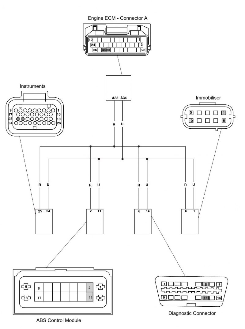
Can fault
| Fault Code | Possible cause | Action |
| CAN fault - lost communication with engine ECM | CAN fault - lost communication with engine ECM | Ensure ABS ECM connector is secure. Proceed to pinpoint test 1: |
| CAN fault - lost communication with instrument panel | CAN fault - lost communication with instrument panel | |
| CAN fault - all communication lost | CAN fault - all communication lost |
Pinpoint tests
| Test | Result | Action | |
| 1 | Check cable and terminal integrity: - ABS ECM connector pin 2 - ABS ECM connector pin 11 | OK | Disconnect instruments and proceed to test 2 |
| Faulty | Rectify fault, proceed to test 5 | ||
| 2 | Check the cable for continuity: - ABS ECM pin 2 to ground - ABS ECM pin 11 to ground | OK | Proceed to test 3 |
| Short circuit | Rectify wiring harness fault, proceed to test 5 | ||
| 3 | Check cable continuity: - ABS ECM pin 2 to ECM pin A33 - ABS ECM pin 11 to ECM pin A34 - ABS ECM pin 2 to Instruments pin 25 - ABS ECM pin 11 to Instruments pin 24 - ABS ECM pin 2 to Diagnostic connector pin 6 - ABS ECM pin 11 to Diagnostic connector pin 14 - ABS ECM pin 2 to Immobiliser module pin 6 - ABS ECM pin 11 to Immobiliser module pin 1 | OK | Proceed to test 4 |
| Open circuit | Rectify wiring harness fault, proceed to test 5 | ||
| 4 | Check cable for short circuit: - ABS ECM pin 2 to ABS ECM pin 11 | OK | Proceed to test 4 |
| Short circuit | Rectify wiring harness fault, proceed to test 5 | ||
| 5 | Clear fault code and test ABS to verify fault cleared. | OK | Action complete - quit test |
| Fault still present | Contact Triumph service | ||
Circuit diagram
ABS ECM internal error
| Fault Code | Possible cause | Action |
| C1681 | ABS ECM internal error Incorrect wheel speed sensor air gap Damaged or dirty pulser ring Loose or incorrectly installed wheel speed sensor | Ensure ABS modulator/ECM connector is secure. Proceed to pinpoint test 1: |
Pinpoint tests
| Test | Result | Action | |
| 1 | Measure the air gap of the wheel speed sensors between the sensor and the pulser ring: - Air gap between 0.40 mm to 1.20 mm | OK | Proceed to test 1 |
| Faulty | Rectify the fault and proceed to test 4 | ||
| 2 | Check the pulser rings for damage or contamination by road grime or ferrous metal filings. | OK | Proceed to test 2 |
| Faulty | Clean or replace the ABS pulser ring, proceed to test 4 | ||
| 3 | Check the wheel speed sensors for correct installation, and the fixings for correct torque. | OK | Proceed to test 4 |
| Faulty | Rectify the fault and proceed to test 4 | ||
| 4 | Clear fault code and test ABS to verify fault cleared. | OK | Action complete - quit test |
| Fault still present | Contact Triumph service | ||
Modulator output (wheel) pressure sensor malfunction
| Fault Code | Possible Cause | Action |
| Modulator output (wheel) pressure sensor malfunction | Modulator output (wheel) pressure sensor malfunction | Contact Triumph service |