System description
This model is fitted with an electronic engine management system which encompasses control of both ignition and fuel delivery. The engine electronic control module (ECM) draws information from sensors positioned around the engine, cooling and air intake systems and precisely calculates ignition advance and fueling requirements for all engine speeds and loads.
In addition, the system has an on-board diagnostic function. For additional information, see System Diagnostics.
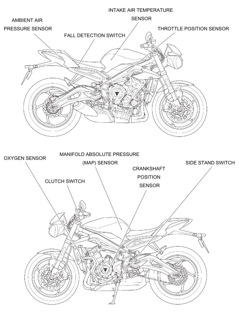
System Sensors
- Intake air temperature sensor - situated on top of the airbox. As the density of the air changes with temperature (therefore the amount of oxygen available to ignite the fuel), an intake air temperature sensor is fitted. Changes in air temperature are compensated for by adjusting the amount of fuel injected to a level consistent with clean combustion and low emissions.
- Ambient air pressure sensor - situated on the battery tray under the seat bridge. The ambient air pressure sensor measures atmospheric air pressure. With this information, the amount of fuel per injection is adjusted to suit the prevailing conditions.
- Manifold Absolute Pressure (MAP) sensor - situated on top of the airbox, connected to each of the three throttle bodies by equal length tubes. The MAP sensor provides information to the engine ECM which is used at shallow throttle angles (very small throttle openings) to provide accurate engine load indications to the ECM. This degree of engine load accuracy allows the ECM to make very small adjustments to fuel and ignition which would otherwise not be possible from throttle angle data alone.
- Clutch switch - situated on the clutch lever. The clutch must be pulled in for the starter motor to operate.
- Crankshaft position sensor - situated in the alternator cover. The crankshaft position sensor detects movement of teeth attached to the alternator rotor. The teeth give a reference point from which the actual crankshaft position is calculated. The crankshaft position sensor information is used by the engine ECM to determine engine speed and crankshaft position in relation to the point where fuel is injected and ignition of the fuel occurs.
- Engine coolant temperature sensor - situated at the rear of the cylinder head near the thermostat housing. Coolant temperature information, received by the engine ECM, is used to optimise fueling at all engine temperatures and to calculate hot and cold start fueling requirements.
- Oxygen sensors - situated in the exhaust header pipe system upstream of the catalytic converter. The oxygen sensors constantly feed information to the engine ECM on the content of the exhaust gases. Based on this information, adjustments to air/fuel ratio are made.
- Side stand switch - situated at the top of the side stand leg. If the side stand is in the down position, the engine will not run unless the transmission is in neutral.
- Fall detection switch - situated under the rider's seat, next to the fuse box. The fall detection switch will detect if the motorcycle is on its side and will cut power to the engine ECM immediately. This prevents the engine from running and the fuel pump from delivering fuel. In the event of a fall, the switch is reset by returning the bike to an upright position and switching the ignition off then back on again.
- Gear position sensor - situated in the lower crankcase, above the drive chain front sprocket. The gear position sensor provides the engine ECM with selected gear information. This is used to prevent the engine from starting if the transmission is in gear. The sensor also provides information to the neutral lamp in the instruments.
- Quickshifter (if fitted) - situated on the gear change linkage. The quickshifter is a momentary action switch which is activated when pressure is applied to the gear change pedal. When activated, the quickshifter will trigger a momentary engine cut to allow gears to engage without closure of the throttle or operation of the clutch. The quickshifter will only operate for up-changes and only then if the engine speed is greater than 2,500 rpm.
Sensor locations
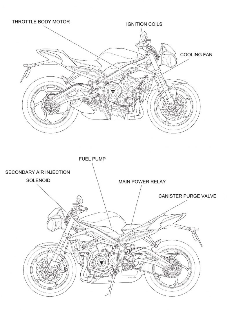
System actuators
In response to signals received from the sensors, the engine ECM controls and directs messages to a series of electronic and electro-mechanical actuators. The function and location of the actuators is given below.
- Throttle actuator motor- situated on the front of the throttle bodies. The throttle actuator motor opens and closes the throttle plates in the throttle bodies, in response to commands from the engine ECM. The throttle actuator motor is an integral part of the throttle bodies.
- Canister purge valve - situated in the vapour return line between the carbon canister and the throttle bodies. The purge valve controls the return of vapour which has been stored in the carbon canister during the period when the engine is switched off. The valve is 'pulsed' by the engine ECM to give control over the rate at which the canister is purged.
- Fuel Injectors - located in the throttle bodies. The engine is fitted with three injectors. The spray pattern of the injectors is fixed but the length of time each injector can remain open is variable according to operating conditions. The duration of each injection is calculated by the engine ECM using data received from the various sensors in the system.
- Ignition coils - plug-top coils are located in the camshaft cover. There are three coils fitted, one for each spark plug. The engine ECM controls the point at which the coils are switched on and off. In calculating the switch-on time, the engine ECM allows sufficient time for the coils to charge to a level where a spark can be produced. The coils are switched off at the point of ignition, the timing of which is optimised for good engine performance.
- Engine Management System (EMS) main relay - situated under the seat. When the ignition is switched on, the EMS main relay is powered up to provide a stable Voltage supply for the engine ECM. When the ignition is turned off, the engine ECM carries out a power down sequence during which the EMS main relay remains powered by the engine ECM for one minute. The engine ECM power down sequence includes: writing the adaption data to engine ECM memory.
- Fuel pump - located inside the fuel tank. The electric pump delivers fuel into the fuel system, via a pressure regulator, at a constant 3.5 bar pressure. The pump is run continuously when the engine is operating and is also run briefly when the ignition is first switched on to ensure that 3.5 bar is available to the system as soon as the engine is cranked. Fuel pressure is controlled by a regulator also situated inside the fuel tank.
- Cooling fan - located behind the radiator. The engine ECM controls switching on and off of the cooling fan in response to a signal received from the coolant temperature sensor. When the coolant temperature rises to a level where the cooling effect of natural airflow is insufficient, the cooling fan is turned on by the engine ECM. When the coolant temperature falls sufficiently, the engine ECM turns the cooling fan off. The fan only becomes operational when the engine is running. It will not operate at any other time.
- Secondary air injection solenoid - located above the camshaft cover. The secondary air injection solenoid controls airflow through the secondary air injection system.
Note: In this system, the starter lockout system (clutch switch, gear position sensor, side stand switch) all operate through the engine ECM.
Actuator locations