
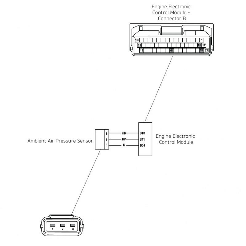
Ambient air pressure sensor
| Fault Code | Possible cause | Action |
| P2228 | Ambient air pressure sensor circuit short circuit to ground | View and note 'freeze-frame' data if available. View and note 'sensor' data. Ensure sensor connector is secure. Disconnect the engine ECM and proceed to pinpoint test 1: |
| P2226 | Ambient air pressure sensor circuit open circuit or short circuit to 5 Volt sensor supply |
Pinpoint Tests
| Test | Result | Action | |
| 1 | Check cable and terminal integrity: - Engine ECM pin B18 - Engine ECM pin B34 - Engine ECM pin B41 - Sensor pin 1, 2, 3 | OK | Disconnect ambient pressure sensor and proceed to test 2 |
| Faulty | Rectify fault, proceed to test 4 | ||
| 2 | Check cable for short circuit: - Engine ECM pin B41 to Engine ECM pin B18 - Engine ECM pin B41 to Engine ECM pin B34 | OK | Proceed to test 3 |
| Short circuit | Locate and rectify wiring fault, proceed to test 4 | ||
| 3 | Check cable for continuity: - Engine ECM pin B34 to sensor pin 3 - Engine ECM pin B18 to sensor pin 1 - Engine ECM pin B41 to sensor pin 2 | OK | Renew ambient pressure sensor and proceed to test 4 |
| Open circuit | Locate and rectify wiring fault, proceed to test 4 | ||
| 5 | Reconnect harness, clear fault code and run engine. | OK | Action complete - quit test |
| Fault still present | Contact Triumph service | ||
Circuit Diagram
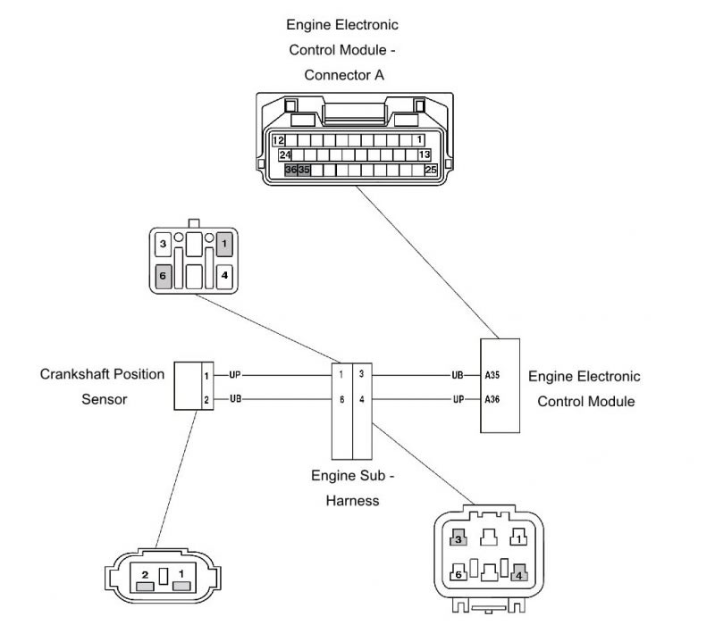
Crankshaft sensor
| Fault Code | Possible cause | Action |
| P0335 | Crankshaft sensor circuit malfunction | View and note diagnostic software freeze frame data if available Ensure sensor is fitted correctly and connector is secure Disconnect ECM and proceed to pinpoint test 1 |
Pinpoint Tests
| Test | Result | Action | |
| 1 | Check terminal and cable integrity: - ECM pin A35 - ECM pin A36 | OK | Disconnect sensor and proceed to test 2 |
| Faulty | Rectify fault, proceed to test 6 | ||
| 2 | Check cable for short circuit: - ECM pin A35 to ground - ECM pin A36 to ground | OK | Proceed to test 3 |
| Short circuit | Locate and rectify wiring fault, proceed to test 6 | ||
| 3 | Check cable continuity: - ECM pin A35 to sensor pin 1 - ECM pin A36 to sensor pin 2 | OK | Proceed to test 4 |
| Open circuit | Locate and rectify wiring fault, proceed to test 6 | ||
| 4 | Check cable for short circuit: - ECM pin A35 to ECM pin A36 | OK | Renew crankshaft sensor, proceed to test 6 |
| Short circuit | Locate and rectify wiring fault, proceed to test 6 | ||
| 5 | Check crank toothed wheel: - Damage to teeth - magnetic debris contamination | OK | Proceed to test 6 |
| Faulty | Clean/renew toothed wheel, proceed to test 6 | ||
| 6 | Reconnect harness, clear fault code and run engine to verify fault cleared. | OK | Action complete - quit test |
| Fault still present | Contact Triumph service | ||
Circuit Diagram
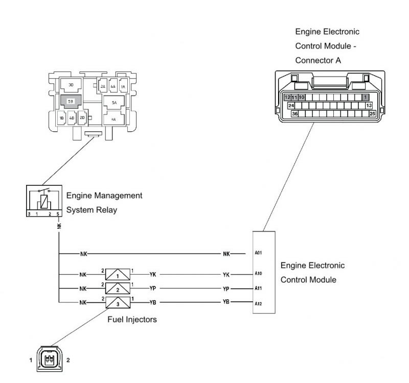
Fuel injectors
| Fault Code | Possible cause | Action |
| P0201 | Injector 1 circuit malfunction | View and note diagnostic software 'freeze-frame' data if available. Ensure relevant injector connector is secure. Disconnect engine ECM and proceed to pinpoint test 1: |
| P0202 | Injector 2 circuit malfunction | |
| P0203 | Injector 3circuit malfunction |
Pinpoint Tests
| Test | Result | Action | |
| 1 | Check cable and terminal integrity: - ECM pin A10 - ECM pin A11 - ECM pin A12 | OK | Proceed to test 2 |
| Faulty | Rectify fault, proceed to test 7 | ||
| 2 | Check resistance value: - ECM pin A01 to ECM pin A10 (injector 1) - ECM pin A01 to ECM pin A11 (injector 2) - ECM pin A01 to ECM pin A12 (injector 3) | OK | Proceed to test 3 |
| Open circuit | Disconnect relevant injector and proceed to test 4 | ||
| Short circuit | Disconnect relevant injector and proceed to test 5 | ||
| 3 | Check cable for short circuit to ground: - ECM pin A10 to ground - ECM pin A11 to ground - ECM pin A12 to ground | OK | Proceed to test 7 |
| Short circuit | Locate and rectify wiring fault, proceed to test 7 | ||
| 4 | Check cable continuity: - EMS relay pin 5 to relevant injector pin 2 - ECM pin A10 to injector 1 pin 1 - ECM pin A11 to injector 2 pin 1 - ECM pin A12 to injector 3 pin 1 | OK | Proceed to test 6 |
| Open circuit | Locate and rectify wiring fault, proceed to test 7 | ||
| 5 | Check cable for short circuit to supply box: - ECM pin A01 to ECM pin A10 (injector 1) - ECM pin A01 to ECM pin A11 (injector 2) - ECM pin A01 to ECM pin A12 (injector 3) | OK | Proceed to test 6 |
| Short circuit | Locate and rectify wiring fault, proceed to test 7 | ||
| 6 | Check relevant injector resistance: - Injector pin 1 to injector pin 2 | 11.4 Ohms to 12.6 Ohms | Proceed to test 7 |
| Faulty | Renew relevant injector, proceed to test 7 | ||
| 7 | Reconnect harness, clear fault code and run engine to verify fault cleared. | OK | Action complete - quit test |
| Fault still present | Contact Triumph service | ||
Circuit Diagram
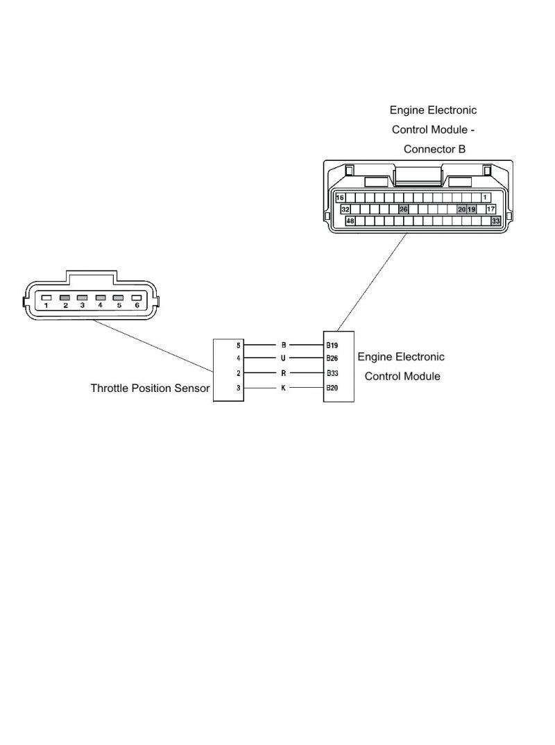
Throttle position sensor
| Fault Code | Possible cause | Action |
| P0120 | Throttle position sensor 1 short circuit to battery Voltage or open circuit | View and note diagnostic software 'freeze-frame' data if available. View and note diagnostic software 'sensor' data. Ensure throttle position sensor connector is secure. Disconnect engine ECM and proceed to pinpoint test 1: |
| P0122 | Throttle position sensor 1 short circuit to ground or open circuit | |
| P0220 | Throttle position sensor 2 short circuit to battery Voltage or open circuit | |
| P0222 | Throttle position sensor 2 short circuit to ground or open circuit | |
| P2135 | Throttle position sensor 1 correlation error with throttle position sensor 2 |
Pinpoint Tests
| Test | Result | Action | |
| 1 | Check cable and terminal integrity: - ECM pin B19 - ECM pin B33 - ECM pin B20 - ECM pin B26 | OK | Disconnect sensor and proceed to test 2 |
| Faulty | Rectify fault, proceed to test 5 | ||
| 2 | Check cable for short circuit: - ECM pin B20 to ground - ECM pin B26 to ground | OK | Proceed to test 3 |
| Short circuit | Locate and rectify wiring fault, proceed to test 5 | ||
| 3 | Check cable continuity: - ECM pin B20 to throttle position sensor connector pin 3 - ECM pin B26 to throttle position sensor connector pin 4 - ECM pin B19 to throttle position sensor connector pin 5 - ECM pin B33 to throttle position sensor connector pin 2 | OK | Proceed to test 4 |
| Open circuit | Locate and rectify wiring fault, proceed to test 5 | ||
| 4 | Check cable for short circuit: - ECM pin B33 to ECM pin B20 - ECM pin B33 to ECM pin B26 | OK | Renew throttle position sensor, proceed to test 5 |
| Short circuit | Locate and rectify wiring fault, proceed to test 5 | ||
| 5 | Reconnect harness, clear fault code and run engine to verify fault cleared. | OK | Action complete - quit test |
| Fault still present | Contact Triumph service | ||
Circuit Diagram
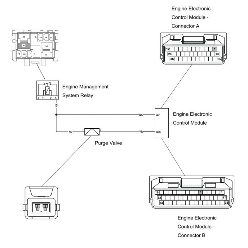
Purge valve
| Fault Code | Possible cause | Action |
| P0443 | Purge valve short circuit to ground or open circuit | View and note diagnostic software 'sensor' data. Ensure purge valve connector is secure. Disconnect engine ECM and proceed to pinpoint test 1: |
| P0459 | Purge valve short circuit to battery Voltage | Disconnect the purge valve and proceed to pinpoint test 5: |
Pinpoint Tests
| Test | Result | Action | |
| 1 | Check cable and terminal integrity: - ECM pin B06 - EMS relay pin 5 | OK | Proceed to test 2 |
| Faulty | Rectify fault, proceed to test 7 | ||
| 2 | Check resistance value: - ECM pin A01 to ECM pin B06 | 22 Ohms to 30 Ohms | Proceed to test 3 |
| Open circuit | Disconnect purge valve and proceed to test 4 | ||
| Short circuit | Disconnect purge valve and proceed to test 5 | ||
| 3 | Check cable for short circuit: - ECM pin B06 to ground | OK | Proceed to test 7 |
| Short circuit | Locate and rectify wiring fault, proceed to test 7 | ||
| 4 | Check cable continuity: - EMS relay pin 5 to valve pin 1 - ECM pin B06 to valve pin 2 | OK | Proceed to test 6 |
| Open circuit | Locate and rectify wiring fault, proceed to test 7 | ||
| 5 | Check cable for short circuit: - ECM pin A01 to ECM pin B06 | OK | Proceed to test 6 |
| Short circuit | Locate and rectify wiring fault, proceed to test 7 | ||
| 6 | Check purge valve resistance: - Valve pin 1 to valve pin 2 | 22 Ohms to 30 Ohms | Proceed to test 7 |
| Faulty | Renew purge valve, proceed to test 7 | ||
| 7 | Reconnect harness, clear fault code and run diagnostic software function test to visually verify operation of purge valve. | OK | Action complete - quit test |
| Fault still present | Contact Triumph service | ||
Circuit Diagram
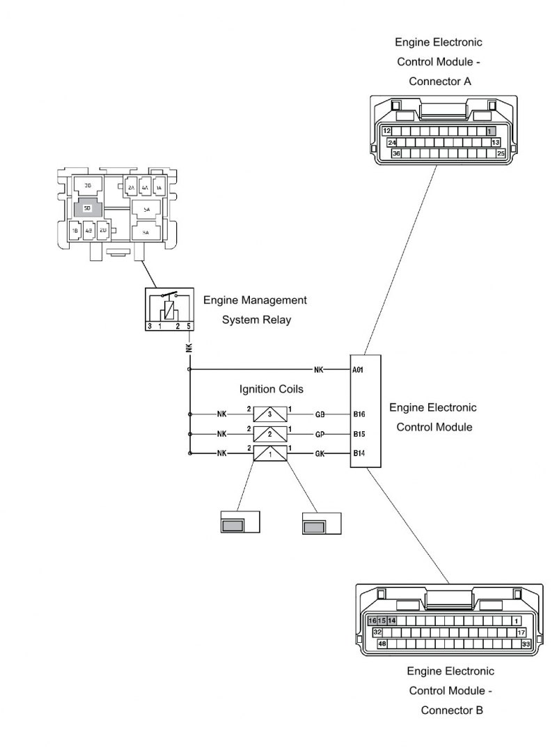
Ignition coils
| Fault Code | Possible cause | Action |
| P0351 | Ignition coil 1 malfunction | View and note diagnostic software 'freeze-frame' data if available. Ensure relevant ignition coil connector is secure. Disconnect engine ECM and proceed to pinpoint test 1: |
| P0352 | Ignition coil 2 malfunction | |
| P0353 | Ignition coil 3 malfunction |
Pinpoint Tests
| Test | Result | Action | |
| 1 | Check cable and terminal integrity: - ECM pin B14 - ECM pin B15 - ECM pin B16 - EMS relay pin 5 | OK | Proceed to test 2 |
| Faulty | Rectify fault, proceed to test 7 | ||
| 2 | Check resistance value: ECM pin A01 to - ECM pin B14 (ignition coil 1) - ECM pin B15 (ignition coil 2) - ECM pin B16 (ignition coil 3) | 3.0 Ohms to 4.2 Ohms | Proceed to test 3 |
| Open circuit | Disconnect relevant ignition coil and proceed to test 4 | ||
| Short circuit | Disconnect relevant ignition coil and proceed to test 5 | ||
| 3 | Check cable for short circuit: - ECM pin B14 to ground - ECM pin B15 to ground - ECM pin B16 to ground | OK | Proceed to test 6 |
| Short circuit | Locate and rectify wiring fault, proceed to test 6 | ||
| 4 | Check cable continuity: - EMS relay pin 5 to relevant ignition coil pin - ECM pin B14 to ignition coil 1 pin 1 - ECM pin B15 to ignition coil 2 pin 1 - ECM pin B16 to ignition coil 3 pin 1 | OK | Proceed to test 5 |
| Open circuit | Locate and rectify wiring fault, proceed to test 6 | ||
| 5 | Check relevant ignition coil resistance: - Ignition coil pin 1 to ignition coil pin 2 | 3.0 Ohms to 4.2 Ohms | Proceed to test 6 |
| Faulty | Renew relevant ignition coil, proceed to test 6 | ||
| 6 | Reconnect harness, clear fault code and run engine to verify fault cleared. | OK | Action complete - quit test |
| Fault still present | Contact Triumph service | ||
Circuit Diagram
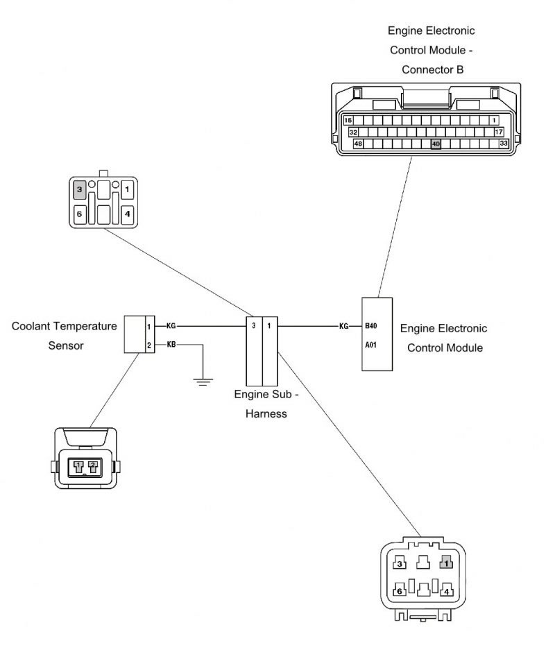
Coolant temperature sensor
| Fault Code | Possible cause | Action |
| P0115 | Engine coolant temperature sensor open circuit or short circuit to 5 Volt sensor supply | View and note diagnostic software freeze frame data if available View and note diagnostic software sensor data Ensure sensor connector is secure Disconnect ECM and proceed to pinpoint test 1 |
| P0117 | Engine coolant temperature sensor short circuit to ground | Disconnect sensor and proceed to test 4 |
Pinpoint Tests
| Test | Result | Action | |
| 1 | Check cable and terminal integrity: - ECM pin B40 | OK | Proceed to test 2 |
| Faulty | Rectify fault, proceed to test 7 | ||
| 2 | Check resistance value: - ECM pin B40 to ground (Temperature dependent - see below) | OK | Disconnect temp sensor and proceed to test 6 |
| Open circuit | Disconnect sensor and proceed to test 3 | ||
| Short circuit | Disconnect temp sensor and proceed to test 4 | ||
| 3 | Check cable continuity: - ECM pin B40 to sensor pin 1 - Ground to sensor pin 2 | OK | Proceed to test 5 |
| Open circuit | Locate and rectify wiring fault, proceed to test 7 | ||
| 4 | Check cable for short circuit: - ECM pin B40 to ground | OK | Proceed to test 5 |
| Short circuit | Locate and rectify wiring fault, proceed to test 7 | ||
| 5 | Check sensor resistance: - Sensor pin 1 to sensor pin 2 (Temperature dependent - see below) | OK | Proceed to test 7 |
| Faulty | Renew temp sensor, proceed to test 7 | ||
| 6 | Reconnect harness, clear fault code and run engine to verify fault cleared. | OK | Action complete - quit test |
| Fault still present | Contact Triumph service | ||
Circuit Diagram
Resistance data under typical conditions:
- Warm engine: 200 to 400 Ohms
- Cold engine:
- 20°C ambient 2.35 to 2.60 K Ohms
- -10°C ambient 8.50 to 10.20 K Ohms
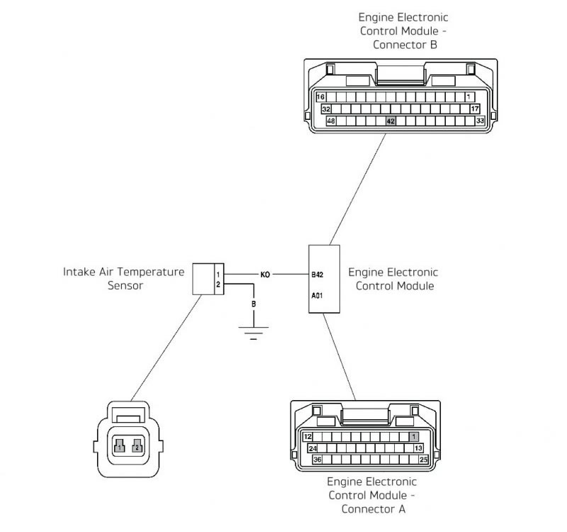
Inlet air temperature sensor
| Fault Code | Possible cause | Action |
| P0110 | Intake air temperature sensor open circuit or short circuit to 5 volt sensor supply | View and note diagnostic software 'freeze-frame' data if available. View and note diagnostic software 'sensor' data. Ensure sensor connector is secure. Disconnect engine ECM and proceed to pinpoint test 1: |
| P0112 | Intake air temperature sensor short circuit to ground | Disconnect engine ECM and sensor and proceed to pinpoint test 6: |
Pinpoint Tests
| Test | Result | Action | |
| 1 | Check cable and terminal integrity: - ECM pin B42 | OK | Proceed to test 2 |
| Faulty | Rectify fault, proceed to test 7 | ||
| 2 | Check resistance value: - ECM pin B42 to ground (Temperature dependent - see below) | OK | Proceed to test 6 |
| Open circuit | Disconnect temp sensor and proceed to test 3 | ||
| Short circuit | Disconnect temp sensor and proceed to test 4 | ||
| 3 | Check cable continuity: - ECM pin B42 to sensor pin 1 - Ground to sensor pin 2 | OK | Proceed to test 5 |
| Open circuit | Locate and rectify wiring fault, proceed to test 7 | ||
| 4 | Check cable for short circuit: - ECM pin B42 to ECM pin A01 - ECM pin B42 to ECM pin B34 | OK | Proceed to test 5 |
| Short circuit | Locate and rectify wiring fault, proceed to test 7 | ||
| 5 | Check sensor resistance: - Sensor pin 1 to sensor pin 2 (Temperature dependent - see below) | OK | Proceed to test 7 |
| Faulty | Renew air temperature sensor, proceed to test 7 | ||
| 6 | Check cable for short circuit: - ECM pin B42 to ground | OK | Proceed to test 7 |
| Short circuit | Locate and rectify wiring fault, proceed to test 7 | ||
| 7 | Reconnect harness, clear fault code and run engine to verify fault cleared. | OK | Action complete - quit test |
| Fault still present | Contact Triumph service | ||
Resistance data:
If engine is warm, remove the sensor and allow time to cool to ambient temperature prior to test.
| Ambient Temperature | Resistance Value |
| 80ºC | 200 to 400 Ohms |
| 20ºC | 2.35 to 2.65 K Ohms |
| -10ºC | 8.50 to 10.25 K Ohms |
Circuit Diagram
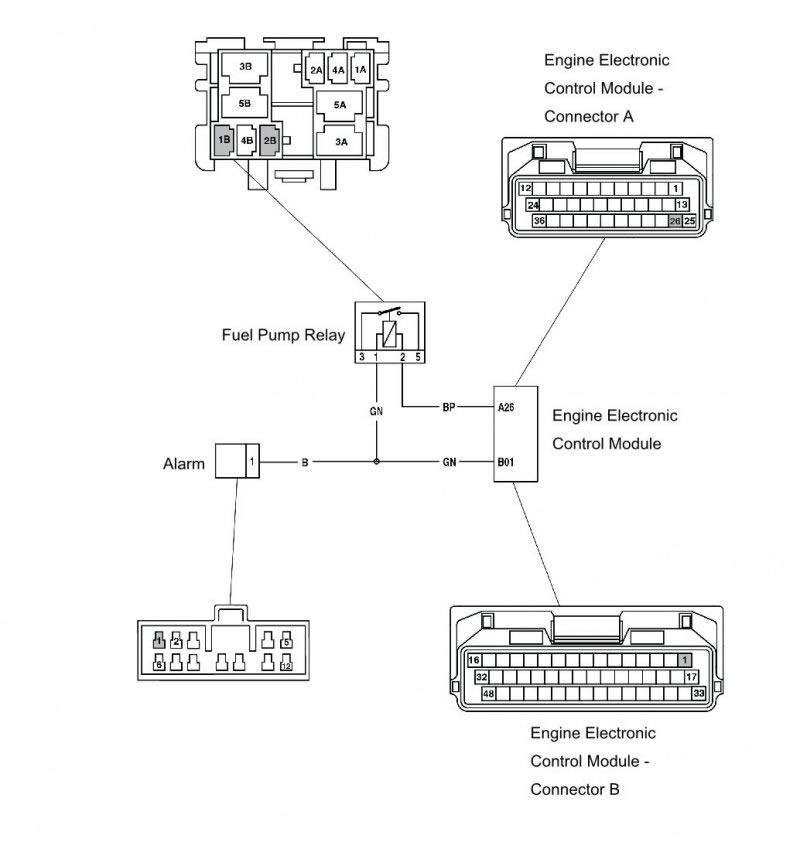
Fuel pump relay
| Fault Code | Possible cause | Action |
| P1231 | Fuel pump relay short circuit to ground or open circuit | Check if pump runs briefly when ignition is switched on Ensure fuel pump relay connector is secure Disconnect ECM and proceed to pinpoint test 1 |
| P1232 | Fuel pump relay short circuit to Vbatt | Disconnect fuel pump relay and proceed to pinpoint test 4 |
Pinpoint Tests
| Test | Result | Action | |
| 1 | Check cable and terminal integrity: - ECM pin A26 - Alarm pin 1 | OK | Disconnect fuel pump relay and proceed to test 2 |
| Faulty | Rectify fault, proceed to test 5 | ||
| 2 | Check cable for short circuit to ground: - ECM pin A26 to ground | OK | Proceed to test 3 |
| Short circuit | Locate and rectify wiring fault, proceed to test 5 | ||
| 3 | Check cable continuity: - ECM pin A26 to fuel pump relay pin 2 - Alarm pin 1 to fuel pump relay pin 1 | OK | Proceed to test 4 |
| Open circuit | Locate and rectify wiring fault, proceed to test 5 | ||
| 4 | Check cable for short circuit: - ECM pin A26 to Alarm pin 1 | OK | Proceed to test 5 |
| Short circuit | Locate and rectify wiring fault, proceed to test 5 | ||
| 5 | Reconnect harness, clear fault code and run diagnostic software function test to verify operation of fuel pump. | OK | Action complete - quit test |
| Fault still present | Contact Triumph service | ||
Circuit Diagram
System voltage
| Fault Code | Possible cause | Action |
| P0560 | Motorcycle voltage system fault | View and note diagnostic software 'sensor' data. Ensure voltage across battery is acceptable, note voltage. |
| Disconnect engine ECM and proceed to pinpoint test 1: |
Pinpoint Tests
| Test | Result | Action | |
| 1 | Check cable and terminal integrity: - ECM pin A01 - ECM pin A13 - EMS relay pin 5 | OK | Proceed to test 2 |
| Faulty | Rectify fault, proceed to test 3 | ||
| 2 | With Ignition on check voltage at: - ECM pin A01 | Same as across battery voltage | Proceed to test 3 |
| Less than across battery voltage | Locate and rectify wiring fault, proceed to test 3 | ||
| 3 | Reconnect harness, clear fault code and run engine to verify fault cleared. | OK | Action complete - quit test |
| Fault still present | Contact Triumph service | ||
Circuit Diagram

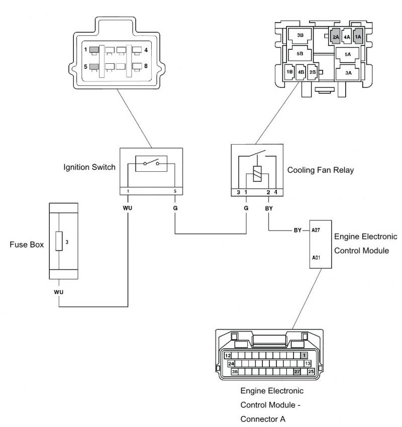
Cooling fan relay
| Fault Code | Possible cause | Action |
| P1552 | Cooling fan relay short circuit to ground or open circuit | View and note diagnostic software 'sensor' data. Ensure fan relay connector is secure. Disconnect engine ECM and proceed to pinpoint test 1: |
| P1553 | Cooling fan relay short circuit to battery Voltage or over temp | Disconnect engine ECM and fan relay and proceed to pinpoint test 4: |
Pinpoint Tests
| Test | Result | Action | |
| 1 | Check cable and terminal integrity: - ECM pin A27 - Cooling fan relay pin 1 - Cooling fan relay pin 2 - Ignition switch pin 5 - Fuse box fuse 3 | OK | Disconnect fan relay and proceed to test 2 |
| Faulty | Rectify fault, proceed to test 5 | ||
| 2 | Check cable for short circuit: - ECM pin A27 to ground | OK | Proceed to test 3 |
| Short circuit | Locate and rectify wiring fault, proceed to test 5 | ||
| 3 | Check cable continuity: - ECM pin A27 to fan relay pin 2 - Ignition pin 5 to fan relay pin 1 | OK | Proceed to test 4 |
| Open circuit | Locate and rectify wiring fault, proceed to test 5 | ||
| 4 | Check cable for short circuit: - ECM pin A27 to ECM pin A01 | OK | Proceed to test 5 |
| Short circuit | Locate and rectify wiring fault, proceed to test 5 | ||
| 5 | Reconnect harness, clear fault code and run diagnostic software function test to visually verify operation of cooling fan. | OK | Action complete - quit test |
| Fault still present | Contact Triumph service | ||
Circuit Diagram
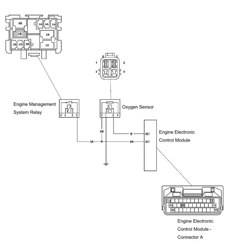
Oxygen sensor
| Fault Code | Possible cause | Action |
| P0130 | Oxygen sensor 1 open circuit or short to ground | View and note 'freeze-frame' data if available. View and note 'sensor' data. Ensure sensor connector is secure. Disconnect engine ECM and proceed to pinpoint test 1: |
| P0131 | Oxygen sensor 1 short circuit to battery Voltage | Disconnect oxygen sensor and proceed to pinpoint test 4: |
Pinpoint Tests
| Test | Result | Action | |
| 1 | Check cable and terminal integrity: - ECM pin A21 | OK | Disconnect oxygen sensors and proceed to test 2 |
| Faulty | Rectify fault, proceed to test 5 | ||
| 2 | Check cable for short circuit: - ECM pin A21 to ground | OK | Proceed to test 3 |
| Short circuit | Locate and rectify wiring fault, proceed to test 5 | ||
| 3 | Check cable continuity: - ECM pin A21 to oxygen sensor pin 2 | OK | Proceed to test 5 |
| Open circuit | Locate and rectify wiring fault, proceed to test 5 | ||
| 4 | Check cable for short circuit: - ECM pin A01 to ECM pin A21 | OK | Renew oxygen sensor and proceed to test 5 |
| Short circuit | Locate and rectify wiring fault, proceed to test 5 | ||
| 5 | Reconnect harness, clear fault code and run engine. Check adaption status. | OK | Action complete - quit test |
| Fault still present | Contact Triumph service | ||
Circuit Diagram
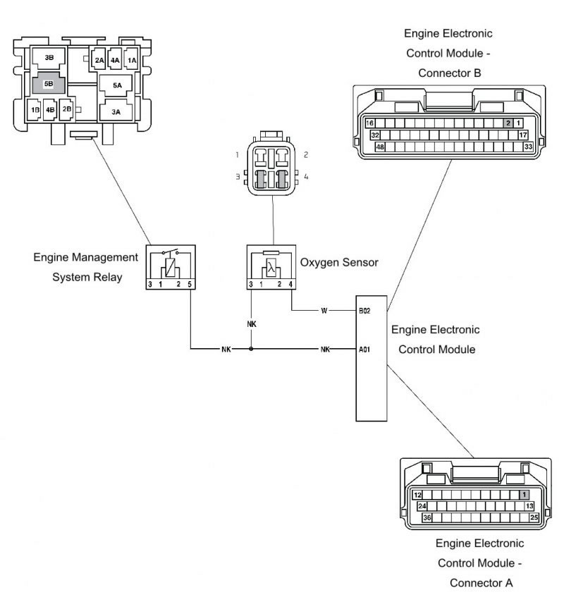
Oxygen sensor heater
| Fault Code | Possible cause | Action |
| P0030 | Oxygen sensor heater 1 circuit malfunction | View and note 'freeze-frame' data if available. View and note 'sensor' data. Ensure sensor connector is secure. Disconnect engine ECM and proceed to pinpoint test 1: |
| P0032 | Oxygen sensor heater ground open circuit or short circuit to battery Voltage |
Pinpoint Tests
| Test | Result | Action | |
| 1 | Check cable and terminal integrity: - ECM pin B02 - EMS relay pin 5 | OK | Disconnect oxygen sensors and proceed to test 2 |
| Faulty | Rectify fault, proceed to test 5 | ||
| 2 | Check cable for short circuit: - ECM pin B02 to ground | OK | Proceed to test 3 |
| Short circuit | Locate and rectify wiring fault, proceed to test 4 | ||
| 3 | Check cable continuity: - ECM pin B02 to oxygen sensor pin 4 - ECM pin A01 to oxygen sensor pin 3 | OK | Proceed to test 4 |
| Open circuit | Locate and rectify wiring fault, proceed to test 4 | ||
| 4 | Check cable for short circuit: - ECM pin A01 to ECM pin B02 | OK | Renew oxygen sensor, proceed to test 5 |
| Short circuit | Locate and rectify wiring fault, proceed to test 5 | ||
| 5 | Reconnect harness, clear fault code and run engine. Check adaption status. | OK | Action complete - quit test |
| Fault still present | Contact Triumph service | ||
Circuit Diagram
Fall detection switch
| Fault Code | Possible cause | Action |
| P1631 | Fall detection circuit short circuit to ground | View and note 'freeze-frame' data if available. View and note 'sensor' data. Ensure switch connector is secure. Disconnect the engine ECM and proceed to pinpoint test 1: |
| P1632 | Fall detection circuit short circuit to battery positive |
Pinpoint Tests
| Test | Result | Action | |
| 1 | Check cable and terminal integrity: - Engine ECM pin B18 - Engine ECM pin B34 - Engine ECM pin B38 - Sensor pin 4, 5, 6 | OK | Disconnect sensor and proceed to test 2 |
| Faulty | Rectify fault, proceed to test 4 | ||
| 2 | Check cable for short circuit: - Engine ECM pin B38 to Engine ECM pin B18 - Engine ECM pin B38 to Engine ECM pin B34 | OK | Proceed to test 3 |
| Short circuit | Locate and rectify wiring fault, proceed to test 4 | ||
| 3 | Check cable continuity: - Engine ECM pin B34 to sensor pin 4 - Engine ECM pin B18 to sensor pin 6 | OK | Proceed to test 4 |
| Open circuit | Locate and rectify wiring fault, proceed to test 4 | ||
| 4 | Reconnect harness, clear fault code. | OK | Action complete - quit test |
| Fault still present | Contact Triumph service | ||
Circuit Diagram

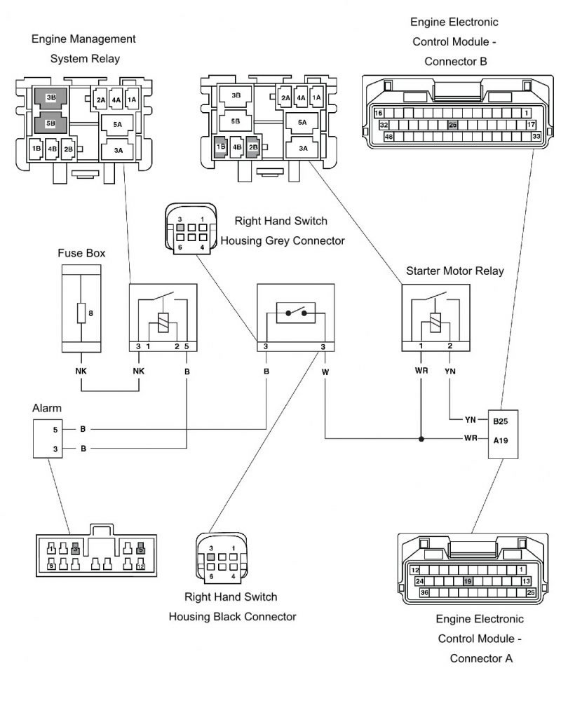
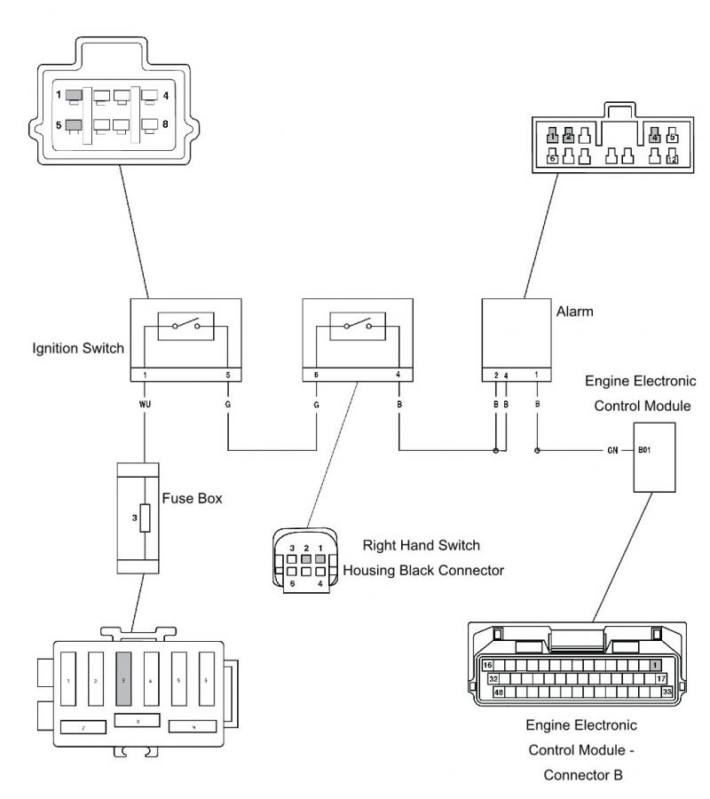
Starter motor relay
| Fault Code | Possible cause | Action |
| P0616 | Starter relay short circuit to ground or open circuit | Ensure starter motor relay connector is secure. Disconnect the engine ECM and proceed to pinpoint test 1: |
| P0617 | Starter relay short circuit to battery Voltage | Disconnect the engine ECM and starter motor relay proceed to pinpoint test 4: |
Pinpoint Tests
| Test | Result | Action | |
| 1 | Check cable and terminal integrity: - ECM pin B25 - ECM pin A19 - Starter Relay pin 1 - Starter Relay pin 2 - fuse box fuse 8 | OK | Disconnect starter relay and proceed to test 2 |
| Faulty | Rectify fault, proceed to test 5 | ||
| 2 | Check cable for short circuit: - ECM pin B25 to ground - ECM pin A19 to ground - ECM pin B25 to ECM pin A01 | OK | Proceed to test 3 |
| Short circuit | Locate and rectify wiring fault, proceed to test 5 | ||
| 3 | To access the black and grey connectors on the right hand switch housing, detach the front brake master cylinder from the handlebar (see Front brake master cylinder - removal). Check cable continuity: | OK | Proceed to test 4 |
| 3.1 - ECM pin B25 to starter relay pin 2 | Open circuit | Locate and rectify wiring fault, proceed to test 4 | |
| 3.2 - ECM pin A19 to starter relay pin 1 | |||
| 3.3 - Fuse box fuse 8 to alarm pin 3 | |||
| 3.4 - Alarm pin 5 - ECM pin A19 | Check the right hand switch housing black and grey connectors are properly inserted and repeat test. If fault still occurs proceed to test 3.5 and 3.6 | ||
| 3.5 - Alarm pin 5 to right hand switch housing grey connector pin 3 | Locate and rectify wiring fault, proceed to test 4 | ||
| 3.6 - Alarm pin 5 to right hand switch housing black connector pin 3 | |||
| 4 | Reconnect harness, clear fault code and run engine to verify fault cleared. | OK | Action complete - quit test |
| Fault still present | Contact Triumph service | ||
Circuit Diagram
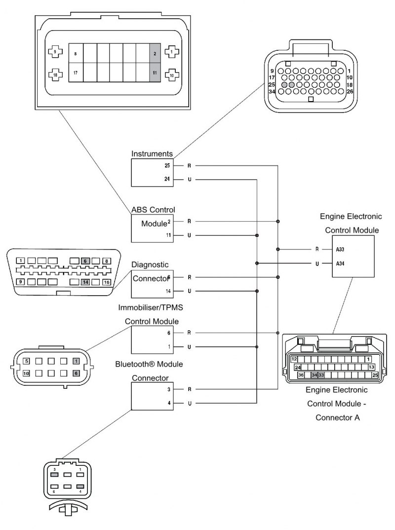
Can communication
| Fault Code | Possible cause | Action |
| P1690 | CAN Fault | View and note 'freeze-frame' data if available. View and note 'sensor' data. Ensure Instrument connector is secure. Disconnect the engine ECM and proceed to pinpoint test 1: |
Pinpoint Tests
| Test | Result | Action | |
| 1 | Check cable and terminal integrity: - ECM pin A34 - ECM pin A33 - Instrument pin 24 - Instrument pin 25 - ABS module pin 2 - ABS module pin 11 - Diagnostic connector pin 6 - Diagnostic connector pin 14 - Immobiliser module pin 1 - Immobiliser module pin 6 - Bluetooth® module pin 3 ‡ - Bluetooth® module pin 4 ‡ | OK | Disconnect instruments and proceed to test 2 |
| Faulty | Rectify fault, proceed to test 5 | ||
| 2 | Check cable for short circuit: - ECM pin A34 to ground - ECM pin A33 to ground | OK | Proceed to test 3 |
| Short circuit | Locate and rectify wiring fault, proceed to test 5 | ||
| 3 | Check cable continuity: - ECM pin A34 to Instrument pin 24 - ECM pin A33 to Instrument pin 25 - ECM pin A34 to ABS control module pin 11 - ECM pin A33 to ABS control module pin 2 - ECM pin A34 to Diagnostic connector pin 14 - ECM pin A33 to Diagnostic connector pin 6 - ECM pin A34 to Immobiliser module pin 1 - ECM pin A33 to Immobiliser module pin 6 - ECM pin A34 to Bluetooth® module pin 4 ‡ - ECM pin A33 to Bluetooth® module pin 3 ‡ | OK | Proceed to test 4 |
| Open circuit | Locate and rectify wiring fault, proceed to test 5 | ||
| 4 | Check cable for short circuit: - ECM pin A34 to ECM pin A33 | OK | Proceed to test 5 |
| Short circuit | Locate and rectify wiring fault, proceed to test 5 | ||
| 5 | Reconnect harness, clear fault code and run engine. | OK | Action complete - quit test |
| Fault still present | Contact Triumph service | ||
| ‡ Bluetooth® is an optional accessory. | |||
Circuit Diagram
Instrument communication (can)
| Fault Code | Possible cause | Action |
| P1695 | Lost communication with instrument panel | View and note 'freeze-frame' data if available. Disconnect engine ECM and proceed to pinpoint test 1: |
Pinpoint Tests
| Test | Result | Action | |
| 1 | Check cable and terminal integrity: - ECM pin A33 - ECM pin A34 - Instrument pin 24 - Instrument pin 25 | OK | Disconnect instruments and proceed to test 2 |
| Faulty | Rectify fault, proceed to test 5 | ||
| 2 | Check cable for short circuit: - ECM pin A33 to ground - ECM pin A34 to ground | OK | Proceed to test 3 |
| Short circuit | Locate and rectify wiring fault, proceed to test 5 | ||
| 3 | Check cable continuity: - ECM pin A33 to Instrument pin 25 - ECM pin A34 to Instrument pin 24 | OK | Proceed to test 4 |
| Open circuit | Locate and rectify wiring fault, proceed to test 5 | ||
| 4 | Check cable for short circuit: - ECM pin A33 to ECM pin A34 | OK | Proceed to test 5 |
| Short circuit | Locate and rectify wiring fault, proceed to test 5 | ||
| 5 | Reconnect harness, clear fault code and run engine. | OK | Action complete - quit test |
| Fault still present | Contact Triumph service | ||
Circuit Diagram

Manifold absolute pressure (map) sensor
| Fault Code | Possible cause | Action |
| P0107 | Manifold absolute pressure sensor 1 short circuit to ground | View and note 'freeze-frame' data if available. View and note 'sensor' data. Ensure sensor connector is secure. Disconnect the engine ECM and proceed to pinpoint test 1: |
| P0105 | Manifold absolute pressure sensor 1 open circuit or short circuit to 5 Volt sensor supply | |
| P1105 | Manifold absolute pressure sensor 1 pipe malfunction | Check connection/condition of pipes from MAP sensors to throttle body. |
Pinpoint Tests
| Test | Result | Action | |
| 1 | Check cable and terminal integrity: - Engine ECM pin B18 - Engine ECM pin B34 - Engine ECM pin B36 - Sensor pin 1, 2, 3 | OK | Disconnect MAP sensors and proceed to test 2 |
| Faulty | Rectify fault, proceed to test 4 | ||
| 2 | Check cable for short circuit: - Engine ECM pin B36 to Engine ECM pin B18 - Engine ECM pin B36 to Engine ECM pin B34 | OK | Proceed to test 3 |
| Short circuit | Locate and rectify wiring fault, proceed to test 4 | ||
| 3 | Check cable for continuity: - Engine ECM pin B34 to MAP sensor pin 3 - Engine ECM pin B18 to MAP sensor pin 1 - Engine ECM pin B36 to MAP sensor pin 2 | OK | Renew relevant MAP pressure sensor, proceed to test 4 |
| Open circuit | Locate and rectify wiring fault, proceed to test 4 | ||
| 4 | Reconnect harness, clear fault code and run engine. | OK | Action complete - quit test |
| Fault still present | Contact Triumph service | ||
Circuit Diagram

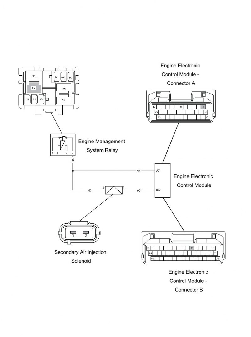
Secondary air injection valve
| Fault Code | Possible cause | Action |
| P0412 | Secondary air injection short circuit to ground or open circuit | View and note diagnostic tool sensor data. Ensure SAI valve connector is secure. Disconnect engine ECM and proceed to pinpoint test 1: |
| P044F | Secondary air injection short circuit to battery Voltage | Disconnect engine ECM and SAI valve and proceed to pinpoint test 5: |
Pinpoint Tests
| Test | Result | Action | |
| 1 | Check cable and terminal integrity: - ECM pin B07 - EMS Relay pin 5 | OK | Proceed to test 2 |
| Faulty | Rectify fault, proceed to test 7 | ||
| 2 | Check resistance value: - ECM pin A01 to ECM pin B07 | 18 Ohms to 24 Ohms | Proceed to test 3 |
| Open circuit | Disconnect SAI valve and proceed to test 4 | ||
| Short circuit | Disconnect SAI valve and proceed to test 5 | ||
| 3 | Check cable for short circuit: - ECM pin B07 to ground | OK | Proceed to test 7 |
| Short circuit | Locate and rectify wiring fault, proceed to test 7 | ||
| 4 | Check cable continuity: - EMS relay pin 5 to SAI valve pin 2 - ECM pin B07 to SAI valve pin 1 | OK | Proceed to test 6 |
| Short circuit | Locate and rectify wiring fault, proceed to test 7 | ||
| 5 | Check cable for short circuit: - ECM pin A01 to ECM pin B07 | OK | Proceed to test 6 |
| Fault still present | Locate and rectify wiring fault, proceed to test 7 | ||
| 6 | Check SAI valve resistance: - SAI valve pin 1 to SAI valve pin 2 | 18 Ohms to 24 Ohms | Proceed to test 7 |
| Faulty | Renew SAI valve, proceed to test 7 | ||
| 7 | Reconnect harness, clear fault code and run diagnostic tool function test to visually verify operation of SAI valve. | OK | Action complete - quit test |
| Fault still present | Contact Triumph service | ||
Gear position sensor
| Fault Code | Possible cause | Action |
| P0914 | Gear position sensor short circuit to ground or open circuit | View and note 'freeze-frame' data if available. View and note 'sensor' data. Ensure sensor connector is secure. Disconnect the engine ECM and proceed to pinpoint test 1: |
| P0917 | Gear position sensor short circuit to 5 Volt sensor supply |
Pinpoint Tests
| Test | Result | Action | |
| 1 | Check cable and terminal integrity: - Engine ECM pin B23 - Engine ECM pin B44 | OK | Disconnect sensor and proceed to test 2 |
| Faulty | Rectify fault, proceed to test 5 | ||
| 2 | Check cable for short circuit: - Engine ECM pin B23 to ground - Engine ECM pin B34 to ground - Engine ECM pin B44 to ground | OK | Proceed to test 3 |
| Short circuit | Locate and rectify wiring fault, proceed to test 5 | ||
| 3 | Check cable continuity: - Engine ECM pin B23 to sensor pin 2 - Engine ECM pin B18 to sensor pin 3 - Engine ECM pin B34 to sensor pin 4 - Engine ECM pin B44 to sensor pin 1 | OK | Proceed to test 4 |
| Open circuit | Locate and rectify wiring fault, proceed to test 5 | ||
| 4 | Check cable for short circuit: - Engine ECM pin B23 to Engine ECM pin B44 - Engine ECM pin B23 to Engine ECM pin B34 | OK | Renew gear position sensor and contact pin and proceed to test 5 |
| Short circuit | Locate and rectify wiring fault, proceed to test 5 | ||
| 5 | Reconnect harness, clear fault code and run engine. | OK | Action complete - quit test |
| Fault still present | Contact Triumph service | ||
Circuit Diagram

Fuel level sensor circuit
| Fault Code | Possible cause | Action |
| P0460 | Fuel level sensor circuit malfunction | View and note 'freeze-frame' data if available. View and note 'sensor' data. Ensure sensor connector is secure. Disconnect engine ECM and proceed to pinpoint test 1: |
Pinpoint Tests
| Test | Result | Action | |
| 1 | Check cable and terminal integrity: - ECM pin B22 | OK | Disconnect sensor and proceed to test 2 |
| Faulty | Rectify fault, proceed to test 4 | ||
| 2 | Check cable for short circuit: - ECM pin B22 to ground | OK | Proceed to test 3 |
| Short circuit | Locate and rectify wiring fault, proceed to test 4 | ||
| 3 | Check cable continuity: - ECM pin B22 to sensor pin 1 - Ground to sensor pin 2 | OK | Proceed to test 4 |
| Open circuit | Locate and rectify wiring fault, proceed to test 4 | ||
| 5 | Reconnect harness, clear fault code. | OK | Action complete - quit test |
| Fault still present | Contact Triumph service | ||
Circuit Diagram

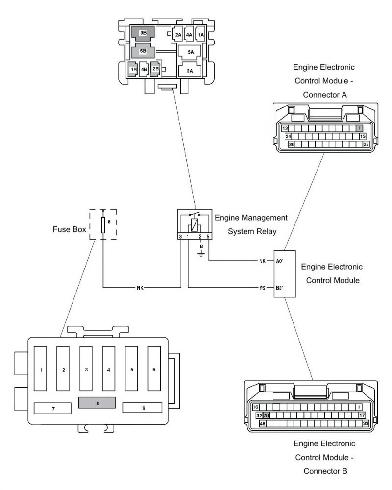
Ems main relay circuit
| Fault Code | Possible cause | Action |
| P1685 | Main relay circuit malfunction | Note that the starter motor cannot be powered if a main relay fault exists. Ensure the EMS main relay connector is secure. Proceed to pinpoint test 1: |
Pinpoint Tests
| Test | Result | Action | |
| 1 | Ensure ignition has been switched off for greater than 90 seconds. Identify EMS main relay on the harness. Check that relay operates when the ignition is switched ON and the stop and run switch is in the RUN position. | OK | Proceed to test 4 |
| Faulty | Disconnect EMS main relay and engine ECM. Proceed to test 4 | ||
| 2 | Check cable for short circuit: - ECM pin B31 to ground - ECM pin A01 to ground | OK | Proceed to test 3 |
| Short circuit | Locate and rectify wiring fault, replace Fuse 5 and proceed to test 6 | ||
| 3 | Check cable and terminal integrity: - ECM pin B31 - EMS main relay pin 1 - EMS main relay pin 2 - EMS main relay pin 3 - EMS main relay pin 5 | OK | Disconnect main relay and proceed to test 4 |
| Faulty | Rectify fault, proceed to test 5 | ||
| 4 | Check fuse box fuse 8 integrity. | OK | Proceed to test 5 |
| Short circuit | Replace fuse and proceed to test 5 | ||
| 5 | Check cable continuity: - ECM pin A01 to EMS main relay pin 5 - ECM pin B31 to EMS relay pin 1 - EMS main relay pin 2 to ground - EMS main relay pin 3 to fuse box fuse 8 | OK | Replace EMS main relay and proceed to test 6 |
| Open circuit | Locate and rectify wiring fault, proceed to test 6 | ||
| 6 | Reconnect harness, clear fault code. Switch ignition off for longer than 90 seconds. Switch ignition on and check that the EMS main relay operates. Start engine as final check. | OK | Action complete - quit test |
| Fault still present | Contact Triumph service | ||
Circuit Diagram
Ems ignition voltage input circuit
| Fault Code | Possible cause | Action |
| P1659 | Ignition power supply malfunction | Disconnect engine ECM and proceed to pinpoint test 1: |
Pinpoint Tests
| Test | Result | Action | |
| 1 | Check fuse box fuse 3 integrity. | OK | Proceed to test 3 |
| Faulty | Proceed to test 2 | ||
| 2 | Check cable for short circuit: - ECM pin B01 to ground | OK | Replace Fuse 3 and proceed to test 3 |
| Short circuit | Locate and rectify wiring fault, replace Fuse 3 and proceed to test 5 | ||
| 3 | Check cable and terminal integrity: - ECM pin B01 - Alarm connector pin 1 - Alarm connector pin 2 - Right hand switch housing pin 6 (black connector) - Right hand switch housing pin 4 (black connector) | OK | Proceed to test 4 |
| Faulty | Rectify fault, proceed to test 5 | ||
| 4 | Check cable continuity: - ECM pin B01 to fuse box fuse 3 Note that the engine stop switch must be in the RUN position and any alarm fitted must be disarmed. | OK | Proceed to test 5 |
| Open circuit | Locate and rectify wiring, immobiliser or engine stop switch fault, proceed to test 5 | ||
| 5 | Reconnect harness, clear fault code and run engine to verify fault cleared. | OK | Action complete - quit test |
| Fault still present | Contact Triumph service | ||
Circuit Diagram
5. volt sensor supply circuit
| Fault Code | Possible cause | Action |
| P1698 | 5V sensor supply malfunction | View and note 'sensor' data. Note engine ECM sensors requiring a power supply will not be active. Disconnect engine ECM and proceed to pinpoint test 1: |
Pinpoint Tests
| Test | Result | Action | |
| 1 | Check cable and terminal integrity: - ECM pin B18 - ECM pin B34 | OK | Proceed to test 2 |
| Faulty | Rectify fault, proceed to test 5 | ||
| 2 | Check cable for short circuit: - ECM pin B18 to ECM pin B34 | OK | Proceed to test 4 |
| Faulty | Proceed to test 3 | ||
| 3 | Disconnect the following sensors in turn: - MAP sensor - Ambient pressure sensor - Fall detection sensor - Gear position sensor and retest for short circuit - ECM pin B18 to ECM pin B34 | OK | Replace sensor last removed and proceed to test 5 |
| Faulty | Proceed to test 4 | ||
| 4 | Check cable for short circuit: - ECM pin B18 to ground - ECM pin B34 to ground - ECM pin B18 to A01 - ECM pin B34 to A01 - ECM pin B18 to battery positive - ECM pin B34 to battery positive | OK | Proceed to test 5 |
| Short circuit | Locate and rectify wiring fault, proceed to test 5 | ||
| 5 | Reconnect harness, clear fault code and use diagnostic software to check for correct sensor outputs and 5 volt sensor supply voltage level. | OK | Action complete - quit test |
| Fault still present | Contact Triumph service | ||
Circuit Diagram

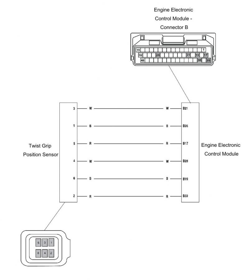
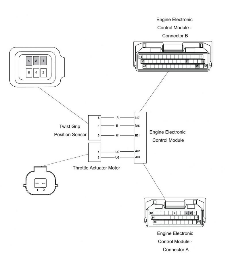
Twist grip position 1
| Fault Code | Possible cause | Action |
| P2120 | Twist grip position sensor 1 short circuit to ground or open circuit | View and note 'sensor' data. Note ECM sensors requiring a power supply will not be active. Ensure twist grip position sensor is secure. Disconnect the engine ECM and proceed to pinpoint test 1: |
| P2123 | Twist grip position sensor 1 short circuit to battery Voltage |
Pinpoint Tests
| Test | Result | Action | |
| 1 | Check cable and terminal integrity: - ECM pin B17 - ECM pin B21 - ECM pin B35 | OK | Disconnect twist grip position sensor and proceed to test 2 |
| Faulty | Rectify fault, proceed to test 5 | ||
| 2 | Check cable for short circuit: - ECM pin B21 to ground | OK | Proceed to test 3 |
| Short circuit | Locate and rectify wiring fault, proceed to test 5 | ||
| 3 | Check cable continuity: - ECM pin B17 to sensor pin 5 - ECM pin B21 to sensor pin 3 - ECM pin B35 to sensor pin 1 | OK | Proceed to test 4 |
| Open circuit | Locate and rectify wiring fault, proceed to test 5 | ||
| 4 | Check cable for short circuit: - ECM pin B21 to ECM pin B17 - ECM pin B21 to ECM pin B35 | OK | Renew twist grip position sensor, proceed to test 5 |
| Short circuit | Locate and rectify wiring fault, proceed to test 5 | ||
| 5 | Reconnect harness, clear fault code and run engine to verify fault cleared. | OK | Action complete - quit test |
| Fault still present | Contact Triumph service | ||
Circuit Diagram
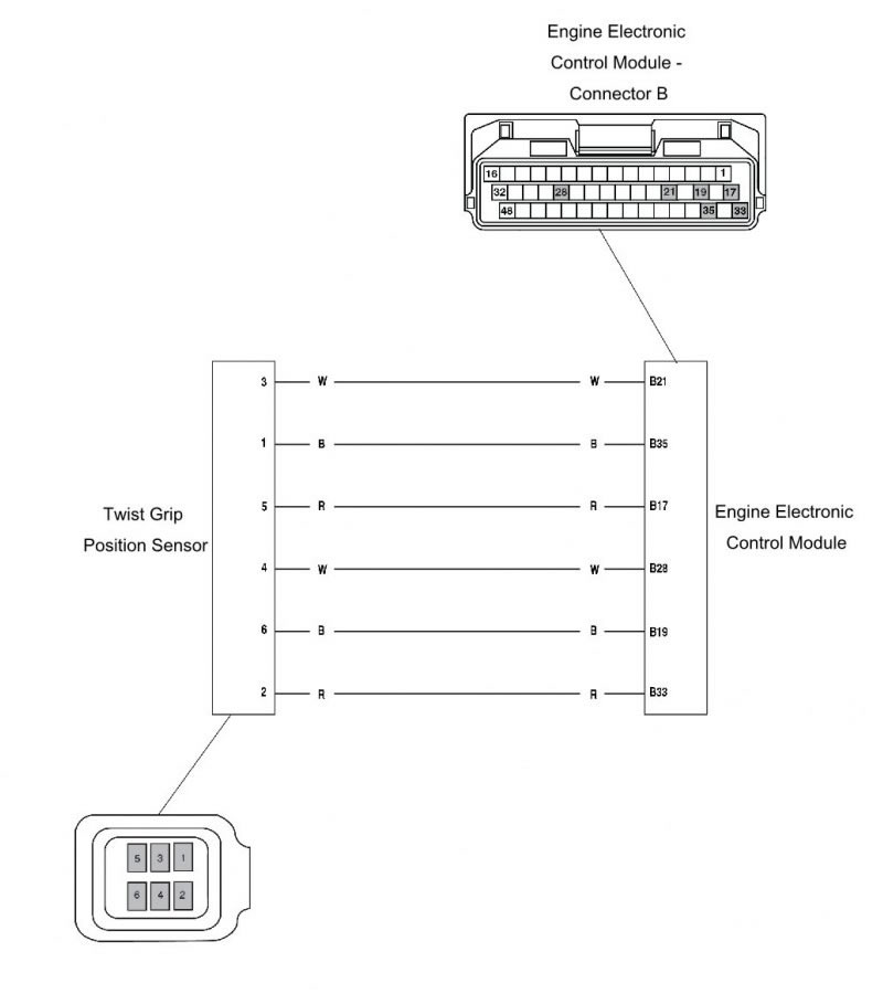
Twist grip position sensor 1 correlation error with twist grip position 2
| Fault Code | Possible cause | Action |
| P2138 | Twist grip position sensor 1 correlation error with twist grip position sensor 2 | View and note diagnostic tool freeze frame data if available. View and note diagnostic tool sensor data. Disconnect twist grip position sensor and proceed to pinpoint test 1: |
Pinpoint Tests
| Test | Result | Action | |
| 1 | Turn the ignition on and measure the Voltage between: - ECM pin B33 and ECM pin B19 - ECM pin B17 and ECM pin B35 (Refer to Technical Bulletin 194 for more information). | 5V DC | Proceed to test 2 |
| Faulty | Rectify fault, proceed to test 2 | ||
| 2 | Check cable continuity: - ECM pin B21 to sensor pin 3 - ECM pin B28 to sensor pin 4 | OK | Renew the twist grip and proceed to test 3 |
| Open circuit | Rectify fault, proceed to test 3 | ||
| 3 | Reconnect harness, clear fault code and run engine to verify fault cleared. | OK | Action complete - quit test |
| Fault still present | Contact Triumph service | ||
Circuit Diagram
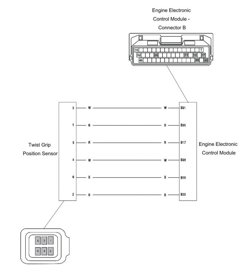
Twist grip position 2
| Fault Code | Possible cause | Action |
| P2125 | Twist grip position sensor 2 short circuit to ground or open circuit | View and note 'sensor' data. Note ECM sensors requiring a power supply will not be active. Ensure twist grip position sensor is secure. Disconnect the engine ECM and proceed to pinpoint test 1: |
| P2128 | Twist grip position sensor 2 short circuit to battery Voltage |
Pinpoint Tests
| Test | Result | Action | |
| 1 | Check cable and terminal integrity: - ECM pin B19 - ECM pin B28 - ECM pin B33 | OK | Disconnect twist grip position sensor and proceed to test 2 |
| Faulty | Rectify fault, proceed to test 5 | ||
| 2 | Check cable for short circuit: - ECM pin B28 to ground | OK | Proceed to test 3 |
| Short circuit | Locate and rectify wiring fault, proceed to test 5 | ||
| 3 | Check cable continuity: - ECM pin B19 to sensor pin 6 - ECM pin B28 to sensor pin 4 - ECM pin B33 to sensor pin 2 | OK | Proceed to test 4 |
| Open circuit | Locate and rectify wiring fault, proceed to test 5 | ||
| 4 | Check cable for short circuit: - ECM pin B28 to ECM pin B19 - ECM pin B28 to ECM pin B33 | OK | Renew twist grip position sensor, proceed to test 5 |
| Short circuit | Locate and rectify wiring fault, proceed to test 5 | ||
| 5 | Reconnect harness, clear fault code and run engine to verify fault cleared. | OK | Action complete - quit test |
| Fault still present | Contact Triumph service | ||
Circuit Diagram
Throttle actuator motor
| Fault Code | Possible cause | Action |
| P2100 | Throttle actuator short circuit to ground or short circuit to battery Voltage Throttle actuator with default spring open circuit | View and note diagnostic tool freeze frame data if available. View and note diagnostic tool sensor data. Ensure accelerator position sensor connector is secure. Disconnect the engine ECM and proceed to pinpoint test 1: |
Pinpoint Tests
| Test | Result | Action | |
| 1 | Check cable and terminal integrity: - ECM pin A02 - ECM pin A03 - Throttle actuator motor connector pin 1 - Throttle actuator motor connector pin 2 | OK | Disconnect accelerator position sensor and proceed to test 2 |
| Faulty | Rectify fault, proceed to test 5 | ||
| 2 | Check cable for short circuit: - ECM pin A02 to ground - ECM pin A03 to ground | OK | Proceed to test 3 |
| Short circuit | Locate and rectify wiring fault, proceed to test 5 | ||
| 3 | Check fuse box fuse 3 integrity. Check cable continuity: - ECM pin B17 to sensor pin 5 - ECM pin B21 to sensor pin 3 - ECM pin B35 to sensor pin 1 | OK | Proceed to test 4 |
| Open circuit | Locate and rectify wiring fault, proceed to test 5 | ||
| 4 | Check cable for short circuit: - ECM pin A02 to ECM pin A01 - ECM pin A03 to ECM pin A01 | OK | Renew twist grip position sensor, proceed to test 5 |
| Short circuit | Locate and rectify wiring fault, proceed to test 5 | ||
| 5 | Reconnect harness, clear fault code and run engine. | OK | Action complete - quit test |
| Fault still present | Contact Triumph service | ||
Circuit Diagram
Immobiliser control module communication
| Fault Code | Possible cause | Action |
| P1650 | Lost communication with Immobiliser ECM | View and note 'freeze-frame' data if available. Ensure immobiliser control module connector is secure. Ensure the ignition switch is turned to the OFF position. Proceed to pinpoint test 1: |
Pinpoint Tests
| Test | Result | Action | |
| 1 | Check cable and terminal integrity: - ECM pin A33 - ECM pin A34 - Immobiliser pin 1 - Immobiliser pin 2 - Immobiliser pin 6 - Immobiliser pin 7 - Immobiliser pin 8 | OK | Disconnect ECM and proceed to test 2 |
| Faulty | Rectify fault, proceed to test 6 | ||
| 2 | Check cable for short circuit: - ECM pin A33 to ground - ECM pin A34 to ground | OK | Disconnect immobiliser, ignition switch and proceed to test 3 |
| Faulty | Locate and rectify wiring fault, proceed to test 6 | ||
| 3 | Check fuse box fuse 3 integrity. | OK | Proceed to test 5 |
| Faulty | Proceed to test 4 | ||
| 4 | Check cable for short circuit: - Immobiliser pin 2 to ground - Immobiliser pin 8 to ground | OK | Proceed to test 5 |
| Faulty | Locate and rectify wiring fault, replace relevant fuse, proceed to test 6 | ||
| 5 | Check cable continuity: - ECM pin A33 to immobiliser pin 6 - ECM pin A34 to Immobiliser pin 1 - Immobiliser pin 7 to ground - Fuse box fuse 3 to immobiliser pin 2 | OK | Proceed to test 6 |
| Fault still present | Locate and rectify wiring fault, proceed to test 6 | ||
| 6 | Reconnect harness, clear fault code and run engine. | OK | Action complete - quit test |
| Fault still present | Contact Triumph service | ||
Circuit Diagram

Abs modulator communication
| Fault Code | Possible cause | Action |
| P1521 | Lost communication with ABS | View and note 'freeze-frame' data if available. Ensure ABS modulator connector is secure. Proceed to pinpoint test 1: |
Pinpoint Tests
| Test | Result | Action | |
| 1 | Check cable and terminal integrity: - ECM pin A33 - ECM pin A34 - ABS modulator pin 2 - ABS modulator pin 10 - ABS modulator pin 11 - ABS modulator pin 18 | OK | Disconnect ECM and proceed to test 2 |
| Faulty | Rectify fault, proceed to test 6 | ||
| 2 | Check cable for short circuit: - ECM pin A33 to ground - ECM pin A34 to ground | OK | Disconnect ABS modulator and proceed to test 3 |
| Faulty | Locate and rectify wiring fault, proceed to test 6 | ||
| 3 | Check fuse box fuses 3 and 7 integrity. | OK | Proceed to test 5 |
| Faulty | Proceed to test 4 | ||
| 4 | Check cable for short circuit: - ABS pin 2 to ground - ABS pin 11 to ground | OK | Proceed to test 5 |
| Faulty | Locate and rectify wiring fault, replace relevant fuse, proceed to test 6 | ||
| 5 | Check cable continuity: - ECM pin A33 to ABS pin 2 - ECM pin A34 to ABS pin 11 - ABS pin 10 to ground - Fuse box fuse 7 to ABS pin 18 - Fuse box fuse 3 to ABS pin 4 | OK | Proceed to test 6 |
| Fault still present | Locate and rectify wiring fault, proceed to test 6 | ||
| 6 | Reconnect harness, clear fault code and run engine. | OK | Action complete - quit test |
| Fault still present | Contact Triumph service |
Circuit Diagram

Brake switches
| Fault Code | Possible cause | Action |
| P0571 | Brake 1 switch malfunction | View and note freeze frame data if available. Ensure brake switches connectors are secure. Ensure battery voltage is greater than 10V. Disconnect engine ECM and proceed to pinpoint test 1: |
| P1576 | Brake 1 switch correlation error with brake switch 2 | |
| P1571 | Brake 2 switch malfunction | |
| P1577 | Brake 2 switch correlation error with brake switch 1 |
Pinpoint Tests
| Test | Result | Action | |
| 1 | Turn ignition on, operate rear brake switch and check brake light operation. | OK | Proceed to test 2 |
| Faulty | Rectify fault, proceed to test 6 | ||
| 2 | Check cable and terminal integrity: - ECM pin A06 - ECM pin A07 - Ignition switch pin 8 | OK | Disconnect front and rear brake switch connectors, proceed to test 3 |
| Faulty | Rectify fault, proceed to test 6 | ||
| 3 | With brakes released, check front and rear brake switch operation: The following should be short circuit: - Front brake switch pin 2 to pin 3 - Rear brake light switch pin 2 to pin 4 - Rear brake light switch pin 1 to pin 3 The following should be open circuit: - Front brake switch pin 1 to pin 3 With the front brake switch pressed the following should be short circuit: - Front brake switch pin 1 to pin 3 The following should be open circuit: - Front brake switch pin 2 to pin 3 With the rear brake switch pressed the following should be short circuit: - Rear brake light switch pin 2 to pin 4 - Rear brake light switch pin 1 to pin 3 | OK | Proceed to test 4 |
| Faulty | Replace relevant brake switch, proceed to test 6 | ||
| 4 | Re-Connect the brake switch connectors. Check cable continuity: - Engine ECM pin A07 to front brake switch pin 1 - Engine ECM pin A06 to rear brake switch pin 2 - Engine ECM pin A07 to brake switch relay pin 4 - Brake switch relay pin 2 to ground - Engine ECM pin A06 to front brake switch pin 2 - Engine ECM pin A06 to ignition switch pin 8 | OK | Proceed to test 5 |
| Open Circuit | Locate and rectify wiring fault, proceed to test 6 | ||
| 5 | Re-Connect the brake switch connectors. With the ignition switch on, measure the following Voltages: - Engine ECM pin A06 to ground - Rear brake switch pin 1 to ground - Rear brake switch pin 2 to ground - Rear brake switch pin 3 to ground - Rear brake switch pin 4 to ground - Brake switch relay pin 3 to ground - Brake switch relay pin 1 to ground - Front brake switch pin 3 to ground - Front brake switch pin 2 to ground | greater than 10V | Proceed to test 6 |
| Less than 10V | Locate and rectify wiring fault, proceed to test 6 | ||
| 6 | Reconnect harness, clear fault code and run engine. | OK | Action complete - quit test |
| Fault still present | Contact Triumph service |
Circuit Diagram
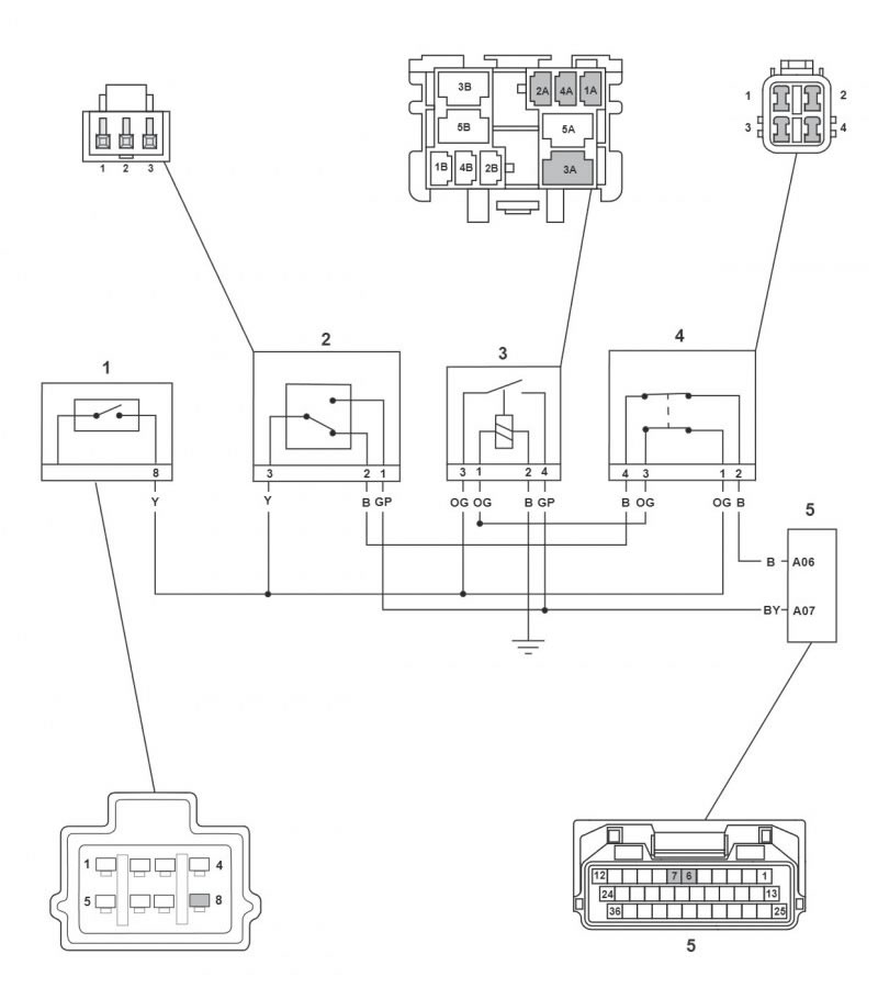
1. Ignition switch; 2. Front brake switch; 3. Brake switch relay; 4. Rear brake switch; 5. Engine Electronic Control Module - Connector A
Headlight relay
| Fault Code | Possible cause | Action |
| P1619 | Headlamp relay short circuit to ground or open circuit | View and note 'freeze-frame' data if available. Disconnect the engine ECM and proceed to pinpoint test 1: |
| P1620 | Headlamp relay short circuit to battery Voltage | Disconnect the engine ECM and headlight relay and proceed to pinpoint test 4: |
Pinpoint Tests
| Test | Result | Action | |
| 1 | Check cable and terminal integrity: - Instruments pin 4 - Headlamp relay high beam pin 1 - Headlamp relay high beam pin 2 - Check fuse box fuses 3 and 9 integrity | OK | Disconnect headlight relay and proceed to test 2 |
| Faulty | Rectify fault, proceed to test 5 | ||
| 2 | Check cable for short circuit: - Instruments pin 4 to ground | OK | Proceed to test 3 |
| Faulty | Locate and rectify wiring fault, replace relevant fuse, proceed to test 5 | ||
| 3 | Check cable continuity: - Instruments pin 4 to headlight relay high beam pin 2 | OK | Proceed to test 4 |
| Faulty | Locate and rectify wiring fault, proceed to test 5 | ||
| 4 | Check cable for short circuit: - Instruments pin 4 to ignition switch pin 5 | OK | Proceed to test 5 |
| Short circuit | Renew headlight relay, proceed to test 5 | ||
| 5 | Reconnect harness, clear fault code and run engine. | OK | Action complete - quit test |
| Fault still present | Contact Triumph service |
Circuit Diagram

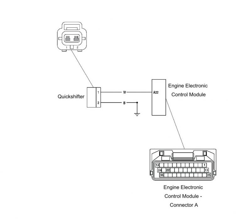
Quickshifter fault
| Fault Code | Possible cause | Action |
| Not applicable Quickshifter not working Quickshifter working intermittently | Quickshifter supply Voltage less than 4.5 V Quickshifter open circuit Quickshifter switch fault | Disconnect engine ECM and proceed to pinpoint test 1 |
Pinpoint Tests
| Test | Result | Action | |
| 1 | Check cable and terminal integrity: - Quickshifter pin 1 - Quickshifter pin 2 | OK | Proceed to test 2 |
| Faulty | Rectify fault, proceed to test 7 | ||
| 2 | Disconnect quickshifter and check Voltage at: - Quickshifter connector pin 1 (motorcycle harness side) | Voltage greater than 4.5 V | Proceed to test 3 |
| Voltage less than or equal to 4.5 V | Contact Triumph service | ||
| 3 | Check cable continuity: - Quickshifter connector pin 2 to ground (motorcycle harness side) | OK | Proceed to test 4 |
| Open circuit | Locate and rectify wiring fault, repeat test 3 | ||
| 4 | Check quickshifter continuity in non activated state across quickshifter terminals: | No continuity | Proceed to test 5 |
| Continuity | Replace quickshifter | ||
| 5 | Check quickshifter continuity in activated state across quickshifter terminals: | Continuity | Proceed to test 6 |
| No Continuity | Replace quickshifter | ||
| 6 | Reconnect quickshifter and ECM connectors and test for correct operation. | OK | Action complete - quit test |
| Fault still present | Contact Triumph service | ||
Circuit Diagram
Eeprom error
| Fault Code | Possible cause | Action |
| P0603 | EEPROM error | View and note 'freeze frame' data if available. No tests available - contact Triumph service. |
Engine ecm internal error
| Fault Code | Possible cause | Action |
| P0606 | Engine ECM internal error | Contact Triumph service. |
| P1607 P1608 | Engine ECM ride by wire internal error |
Traction control disabled due to abs malfunction
| Fault Code | Possible cause | Action |
| P1135 | Traction Control disabled due to malfunction | Check that there is no other DTC linked to the ABS system or CAN communication stored. Contact Triumph service. |
Throttle valve drive error
| Fault Code | Possible cause | Action |
| P2111 | Throttle valve drive error (stuck open) | View and note 'freeze-frame' data if available. View and note 'sensor' data. Check throttle body for mechanical malfunctions. Clear fault code and contact Triumph service if fault is still present. |
| P2119 | Throttle valve drive error | |
| P2102 | Throttle actuator control internal motor relay does not operate | |
| P2103 | Throttle actuator control internal motor relay operates continually |
ECM locked by the calibration lock function
| Fault Code | Possible cause | Action |
| P1605 | Engine ECM locked by the calibration lock function | This is also identified by a fast flashing MIL indication, and a disabled engine management system. Unlock the engine ECM using the diagnostic software and supplied unlock code from Triumph service. |
Instrument id incompatible
| Fault Code | Possible cause | Action |
| P1614 | Instrument ID incompatible | This is also identified by a fast flashing MIL indication, and a disabled engine management system. |
Pinpoint Tests
| Test | Result | Action | |
| 1 | Check engine ECM part number is correct for the motorcycle. | OK | Proceed to test 2 |
| Incorrect | Replace engine ECM with correct part and proceed to test 3 | ||
| 2 | Check that the calibration is correct for the motorcycle, using the diagnostic software. | OK | Proceed to test 3 |
| Incorrect | Update calibration using diagnostic software, proceed to test 3 | ||
| 3 | Clear fault code, check for normal operation. | OK | Action complete - quit test |
| Fault still present | Contact Triumph service | ||
ABS modulator id incompatible
| Fault Code | Possible cause | Action |
| P1520 | Unmatched ABS module | This is also identified by ABS warning light indication. Proceed to pinpoint test 1: |
Pinpoint Tests
| Test | Result | Action | |
| 1 | Check ABS modulator part number is correct for the motorcycle. | OK | Proceed to test 2 |
| Incorrect | Replace ABS modulator with correct part and proceed to test 3 | ||
| 2 | Check that the engine ECM calibration is correct for the motorcycle, using the diagnostic tool. | OK | Proceed to test 3 |
| Incorrect | Update calibration using service tool, proceed to test 3 | ||
| 3 | Clear fault code, check for normal operation. | OK | Action complete - quit test |
| Fault still present | Contact Triumph service |
Engine ecm tamper detected
| Fault Code | Possible cause | Action |
| P1604 | Engine ECM tamper detected - return to Triumph | Contact Triumph service |
Fault finding – non electrical
| Symptom | Possible cause(s) |
| Poor throttle response at low rpm | Low fuel pressure caused by filter blockage/leaks |
| Low fuel pressure caused by loose fuel pipes to the fuel pump and filter | |
| Cutting out at idle | Throttle bodies out of balance |
| Low fuel pressure caused by loose fuel pipes to the fuel pump and filter | |
| Low fuel pressure | |
| Weak mixture caused by air leak at the throttle body/transition piece to cylinder head face | |
| Idle speed too low/high | Incorrect closed throttle position setting |
| Diagnostic software malfunctions during tune download procedure | Low battery voltage |
| Throttle hang-up | Incorrect closed throttle position setting |
| Motorcycle will start but cuts out immediately | Low fuel pressure caused by loose fuel pipes to the fuel pump and filter |
| Low fuel pressure caused by filter blockage/leaks | |
| Abnormally high fuel pressure | Fuel pressure regulator inoperative |
| Temperature gauge reads cooler than normal | Cooling system air–locked resulting in coolant temperature sensor operating in air instead of coolant Thermostat fault |
| Motorcycle will not start | Check the immobiliser system for faults |
| Make sure that the keys, Engine ECM and Chassis ECM are all correctly paired |
Vehicle speed sensor
| Fault Code | Possible cause | Action |
| P0500 | Wheel speed sensor fault | Refer to the following ABS DTCs. |