
Warning! Make sure the motorcycle is stabilised and adequately supported. A correctly supported motorcycle will help prevent it from falling. An unstable motorcycle may fall, causing injury to the operator or damage to the motorcycle.
Perform the following operations:
- Seat - removal
- Battery - removal
- Fuel tank - removal
- Airbox - removal
- Throttle bodies/injectors - removal
- Side panel - removal
- Front sprocket cover - removal
- Side stand switch - removal
- Coolant replacement - drainage
- Radiator - removal
- Coolant expansion tank - removal
Note: Secure the coolant hoses to prevent damage as the engine is removed.
Caution! To prevent chain damage, do not allow the chain to come into contact with dirt, road grit etc.
1. If required, drain the engine oil (see Oil and oil filter change).
2. Set the drive chain adjustment to allow maximum free play in the chain (see Final drive chain Free-Movement Adjustment).
3. Disconnect the gear position sensor from the main harness.
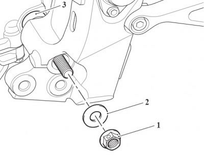
4. Release the pinch bolt and remove the gear change linkage from the gearbox shaft.
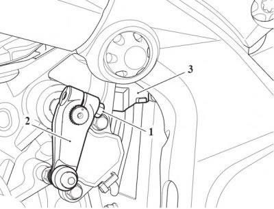
1. Pinch bolt; 2. Gear pedal crank; 3. Gear position sensor connector
5. Release the fixings and detach the two harness brackets and purge valve bracket from the engine breather cover.
6. Ease the rubber boot from the battery ground cable, Release the fixing and detach the ground cables from the frame.

1. Harness brackets; 2. Fixings; 3. Rubber boot; 4. Ground cable fixing; 5. Purge valve bracket (purge valve shown removed for clarity)
Note: Note the routing of the crankshaft position sensor harness for installation.
7. Disconnect the crankshaft position sensor from the main harness.
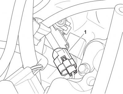
1. Crankshaft position sensor connector
Note: Note the routing of the alternator harness for installation.
8. Disconnect the grey connector from the regulator/rectifier. Route the harness back to the top of the engine.
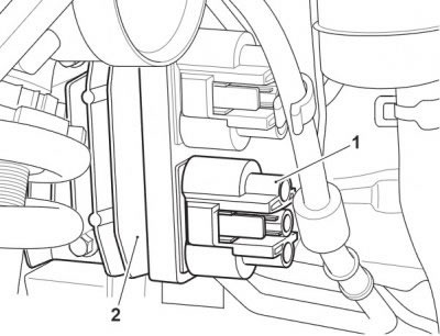
1. Grey connector; 2. Regulator/rectifier
9. Disconnect all the remaining electrical connections from the main harness to the engine.
10. Disconnect the clutch cable from the clutch (see Clutch cable - removal).
11. Place a support beneath the engine and ensure that the frame is still adequately and securely supported.
Note: Note the position of the spacer installed to the lower gearbox bolt, left hand side of the engine.
12. Remove the cover for the gearbox upper mounting on the left hand side of the frame.
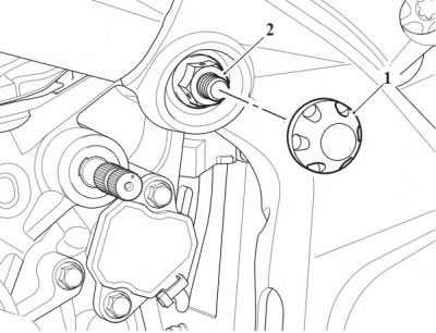
1. Cover; 2. Gearbox upper mounting
13. Release the nuts securing the gearbox mounting bolts and remove the two bolts. Collect the washers and collect the spacer from the lower bolt.
1. Nut; 2. Washer; 3. Spacer
14. Release the nut securing the left hand front engine mounting bolt and remove the bolt.
15. Remove the left hand centre engine mounting bolt.
Note: The frame is fitted with four frame adjuster sleeves, located on the left hand side of the frame, as shown below.
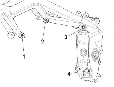
1. Front frame adjuster position; 2. Centre frame adjuster position; 3. Rear upper frame adjuster position; 4. Rear lower frame adjuster position
16. Using T3880103 - Engine Mounting Adjuster, loosen the rear upper frame adjuster sleeve.
17. Using T3880181 - Wrench Frame Adjuster, loosen the rear lower frame adjuster sleeve.
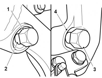
1. T3880103 - Engine Mounting Adjuster; 2. Rear upper frame adjuster; 3. T3880181 - Wrench Frame Adjuster; 4. Rear lower frame adjuster
18. Using T3880103 - Engine Mounting Adjuster, loosen the centre and front frame adjuster sleeves.
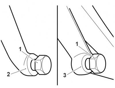
1. T3880103 - Engine Mounting Adjuster; 2. Front frame adjuster; 3. Centre frame adjuster
19. Remove the two remaining (right hand) engine mounting bolts and lower the engine sufficiently to allow the drive chain to be detached from the output sprocket.
20. Remove the engine from the frame.
Caution! To prevent damage to components, lower the engine very carefully.