
Removing and installing valves
Caution! Do not scratch sealing face on cylinder head. Place the head on a clean, non-scratching surface.
Mount valve spring compressor, BMW No. 115690, onto cylinder head.
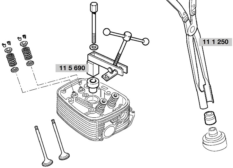
Compress the valve springs.
Gently tap valve head to release collets from spring retainer.
Remove valve collets.
Relieve tension on valve springs.
Remove top and bottom spring retainers, valve springs and valves.
Removing valve stem seals
Pull off valve stem seal with pliers, BMW No. 11 1 250.
Note: If a valve is removed, the valve stem seal must be replaced.
Checking valves for wear
Remove combustion residue from valves.
Check valve dimensions — see Technical Data.
Remachining valve seat
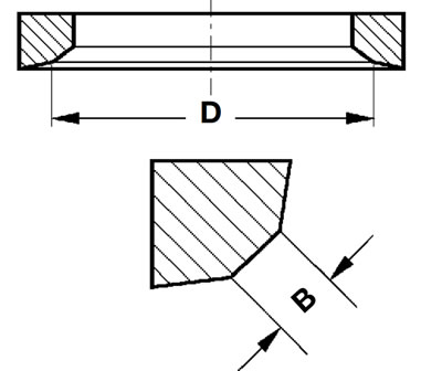
Caution: Width (B) and diameter (D) must always be maintained if valve seat is machined. See Technical Data.
Checking and repairing cylinder head
Remove combustion residues from combustion chamber.
Check sealing face for damage/distortion, and skim flat if necessary.
Skimming sealing face: max. 0.2 mm (0.008 in) metal removal
Checking valve guide for wear
Check valve guide bore — see Technical Data.
Replacing valve guides
Heat cylinder head slowly and uniformly to 200°C (392°F) in a suitable oven.
Caution! Wear protective gloves when handling heated parts.
Drive out valve guides with 5 mm (0.1969 in) dia. drift, BMW No. 11 5 674, from the combustion chamber side.
Allow cylinder head to cool down to room temperature (approx. 20°C/68°F).
Examine valve guide bore for:
- wear,
- widening taper and
- correct dimensions in H7 tolerance range (12.500...12.518 mm/0.4921...0.4928 in).
Note: Valve guides are press-fitted in the cylinder head with an interference fit of 0.015...0.044 mm (0.0006...0.0017 in).
If valve guide bore is undamaged and dimensions are within correct 12.5 H7 tolerance range:
- Use original 12.5 U6 (12.533...12.544 mm/ 0.4934...0.4939 in) valve guide.
- Measure valve guides with micrometer.
If valve guide bore is undamaged but slightly larger than the 12.5 H7 tolerance range:
- Use replacement valve guide 12.550...12.561 mm (0.4941...0.4945 in).
If valve guide bore is damaged or not to correct dimensions in 12.5 H7 tolerance range:
- Use an oversize 12.7 U6 (12.733...12.744 mm/ 0.5013...0.5017 in) valve guide.
Repair method 1 - ream out the bore (if bore is damaged or not to correct dimensions)
Determine actual diameter of valve guide using micrometer.
Ream bore with 012.7 H7 mm (12.700...12.718 mm/0.5000...0.5007 in) reamer.
Repair method 2 - turn the valve guide on a lathe (only if bore is undamaged)
Measure bore with internal measuring tool.
Calculate the nominal diameter of the valve guide:
Required diameter of valve guide = bore dia. + interference-fit value (0.015...0.044 mm/0.0006...0.0017 in).
Use an oversize 12.7 U6 (12.733...12.744 mm/0.5013...0.5017 in) valve guide.
Machine oversize valve guide to required diameter.
Slowly heat cylinder head to 200°C (392°F) in a suitable oven.
Immerse valve guide in liquid grinding talc.
Chill valve guide with dry ice.
Caution! Immediately before pressing in, the temperature must be -40°C (-40°F).
Place heated cylinder head flat on workbench or a similar surface.
Mount the chilled valve guide on ∅5 mm (0.1969 in) drift, BMW No. 11 5 673.
Drive valve guides into cylinder head with no delay.
Allow cylinder head to cool down to room temperature, approx. 20°C (68°F).
Inspect bores of valve guides.
Note: Valve guides for repair purposes are produced with an internal diameter of 5.01 mm (0.1972 in) H7. In most cases, the bore is within the 5.00 mm (0.1969 in) H7 tolerance range after pressing in. If the bore is too narrow, ream it out to size.
Installing valve and valve stem seal
Note: If a valve was removed, the valve stem seal must be replaced.
Oil the stem when installing the valve.
Shrink a short length of tube (arrow) on to the end of the valve stem.
Install the valve stem seal with a 5 mm (0.1969 in) dia. drift, BMW No. 11 5 602.

Caution! Remove the shrink-fit tube.
Install lower spring retainer, valve spring and upper spring retainer.
Compress the valve springs with the valve spring compressor, BMW No. 11 5 690.
Note: Apply grease to valve collets (to facilitate installation) and install.
Caution! Make sure that valve collets are correctly seated in the valve stem grooves.
Relieve tension on valve springs.
Check valves for leakage (blow-by).