Camshaft Removal
Remove:
- Cylinder Head Cover (See Cylinder Head Cover Removal)
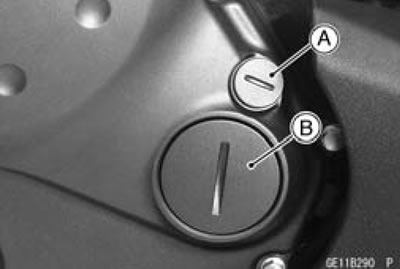
- Timing Inspection Cap [A]
- Timing Rotor Bolt Cap [B]
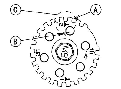
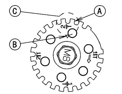
- Using a wrench on the timing rotor bolt, turn the crankshaft clockwise until the 2/T mark line [A] on the timing rotor is aligned with the notch [B] in the edge of the timing inspection hole [C] in the clutch cover.
If the clutch cover is removed, perform the next procedure.
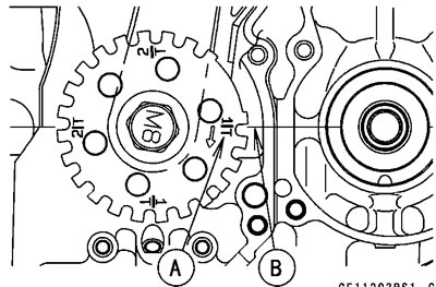
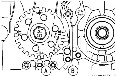
Using a wrench on the timing rotor bolt, turn the crankshaft clockwise until the 1/T mark line [A] on the timing rotor is aligned with the mating surface [B] of the crankcase front side.
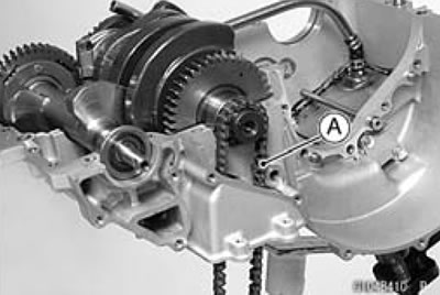
- Remove the camshaft chain tensioner (See Camshaft Chain Tensioner Removal).
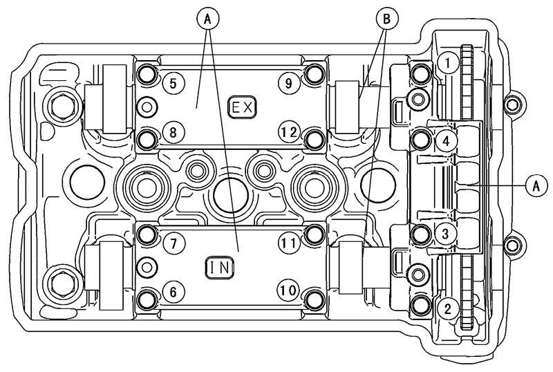
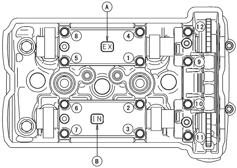
- Loosen the camshaft cap bolts as shown sequence [1-12 ] in the figure, and remove them.
Remove:
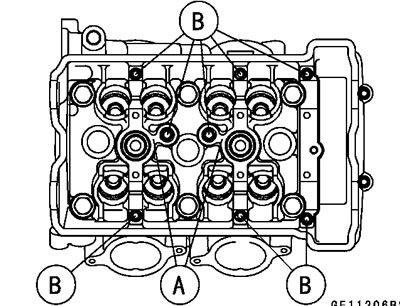
- Camshaft Caps [A]
- Camshafts [B]
Caution: The crankshaft may be turned while the camshafts are removed. Always pull the chain taut while turning the crankshaft. This avoids kinking the chain on the lower (crankshaft) sprocket. A kinked chain could damage both the chain and the sprocket.
- Stuff a clean cloth into the chain tunnel to keep any parts from dropping into the crankcase.
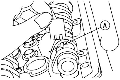
- Remove the cam sprocket mounting bolts [A].
- Remove the cam sprocket.
Camshaft Installation
- Replace the plug hole gaskets [A] with new ones.
- Be sure to install the following parts.
Plug Hole Gaskets
- Dowel Pins [B]
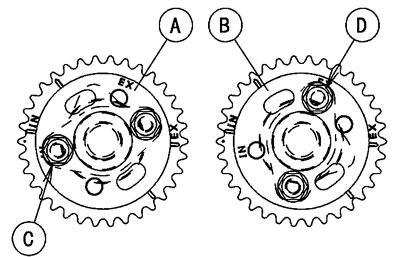
- Install the cam sprockets so that the marked ("IN" and "EX") side faces to the outward.
The inlet [A] and exhaust cam sprockets [B] are identical.
Caution: Inlet cam sprocket must use "IN" marked bolt holes [C]. Exhaust cam sprocket must use "EX" marked bolt holes [D].
- Apply a non-permanent locking agent to the camshaft sprocket bolts and tighten them.
Torque - Camshaft Sprocket Bolts: 15 N·m (1.5 kgf·m, 11 ft·lb)
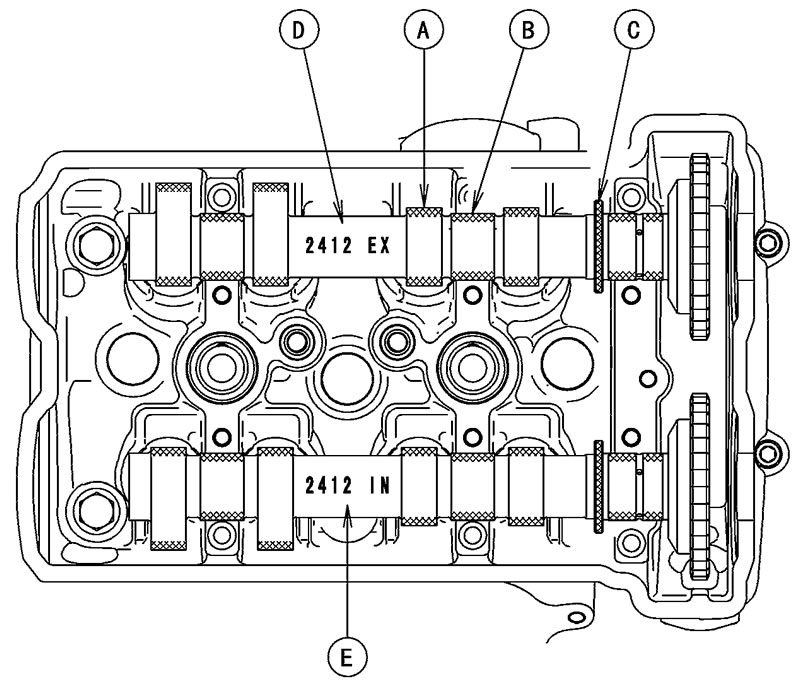
- Apply molybdenum disulfide oil solution to all cams [A], journals [B] and thrust blocks [C] with x marks.
If a new camshaft is to be used, apply a thin coat of molybdenum disulfide grease to the cam surfaces.
Note: The exhaust camshaft has a 2412 EX mark [D] and the inlet camshaft has a 2412 IN mark [E]. Be careful not to mix up these shafts.
- Using a wrench on the timing rotor bolt, turn the crankshaft clockwise until the 2/T mark line [A] on the timing rotor is aligned with the notch [B] in the edge of the timing inspection hole [C] in the clutch cover.
Caution: The crankshaft may be turned while the camshafts are removed. Always pull the chain taut while turning the crankshaft. This avoids kinking the chain on the lower (crankshaft) sprocket. A kinked chain could damage both the chain and the sprocket.
If the clutch cover is removed, perform the next procedure.
Using a wrench on the bolt, turn the crankshaft clockwise until the 1/T mark line [A] on the timing rotor is aligned with the mating surface [B] of the crankcase front side.
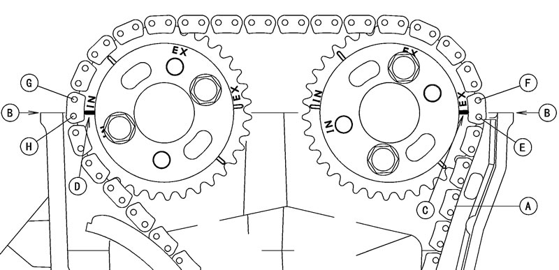
- Pull the tension side (exhaust side) [A] of the chain taut to install the chain.
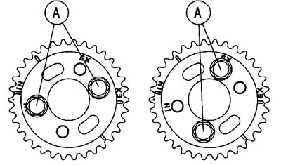
- Engage the camshaft chain with the camshaft sprockets so that the timing marks on the sprockets are positioned as sown.
The timing marks must be aligned with the cylinder head upper surface [B].
- EX Mark [C] (Between #1 Pin and #2 Pin)
- IN Mark [D] (Between #31 Pin and #32 Pin)
- #1 Pin [E]
- #2 Pin [F]
- #31 Pin [G]
- #32 Pin [H]
- Before installing the camshaft caps, install the camshaft chain tensioner body temporally (See Camshaft Chain Tensioner Installation).
- Install the camshaft caps as shown.
Note: The exhaust cap has a "EX" mark [A] and the inlet cap has a "IN" mark [B]. Be careful not to mix up these caps.
- First tighten the camshaft cap bolts [9-12] evenly to seat the camshaft in place, then tighten all bolts following the specified tightening sequence.
Torque - Camshaft Cap Bolts (1-12): 12 Nm (1.2 kgf·m, 106 in·lb)
- Install the camshaft chain tensioner (See Camshaft Chain Tensioner Installation).
- Turn the crankshaft 2 turns clockwise to allow the tensioner to expand and recheck the camshaft chain timing.
- Replace the O-ring of the timing inspection cap and timing rotor bolt cap with new ones.
- Apply grease to the new O-rings.
- Install the timing inspection cap and timing rotor bolt cap.
Torque - Timing Inspection Cap: 3.9 Nm (0.40 kgf·m 35 in·lb)
Timing Rotor Bolt Cap: 4.9 N·m (0.50 kgf·m 43 in·lb)
- Install the cylinder head cover (See Cylinder Head Cover Installation).
Camshaft, Camshaft Cap Wear
- Remove the camshaft caps (See Camshaft Removal).
- Cut strips of plastigage to journal width. Place a strip on each journal parallel to the camshaft installed in the correct position.
- Tighten the camshaft cap bolts to the specified torque (See Camshaft Installation).
Note: Do not turn the camshaft when the plastigage is between the journal and camshaft cap.
- Remove the camshaft cap again, measure each clearance between the camshaft journal and the camshaft cap using plastigage (press gauge) [A].
Camshaft Journal, Camshaft Cap Clearance
Standard: 0.028-0.071 mm (0.0011-0.0028 in.)
Service Limit: 0.16 mm (0.0063 in.)
If any clearance exceeds the service limit, measure the diameter of each camshaft journal with a micrometer.
Camshaft Journal Diameter
Standard: 23.950-23.972 mm (0.9429-0.9438 in.)
Service Limit: 23.92 mm (0.942 in.)
If the camshaft journal diameter is less than the service limit, replace the camshaft with a new one and measure the clearance again.
If the clearance still remains out of the limit, replace the cylinder head unit.
Camshaft Runout
- Remove the camshaft (See Camshaft Removal).
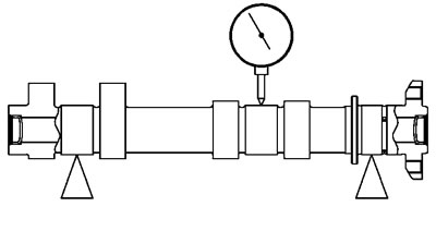
- Set the camshaft in a camshaft alignment jig or on V blocks.
- Measure runout with a dial gauge at the specified place as shown.
If the runout exceeds the service limit, replace the shaft.
Camshaft Runout
Standard: TIR 0.02 mm (0.0008 in.) or less
Service Limit: TIR 0.1 mm (0.004 in.)
Cam Wear
- Remove the camshaft (See Camshaft Removal).
- Measure the height [A] of each cam with a micrometer.
If the cams are worn down past the service limit, replace the camshaft.
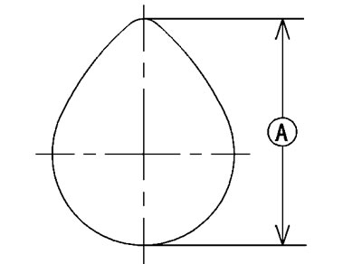
Cam Height
Standard:
- Exhaust 35.343-35.457 mm (1.3915-1.3959 in.)
- Inlet 35.843-35.957 mm (1.4111-1.4156 in.)
Service Limit:
- Exhaust 35.24 mm (1.387 in.)
- Inlet 35.74 mm (1.407 in.)
Camshaft Chain Removal
- Split the crankcase (See Crankcase Splitting in the Crank-shaft/Transmission chapter).
- Remove the camshaft chain [A] from the crankshaft sprocket.