
Removal/installation
Remove the seat (page 2-2).
Remove the rubber band and remove the ECM from the battery tray cover.
Disconnect the ECM 22P black and 22P gray connectors.

Power/ground line inspection
Connect the test harness between the main wire harness and ECM (page 5-8).
Tool: ECU test harness 07YMZ-0010100 (two required).
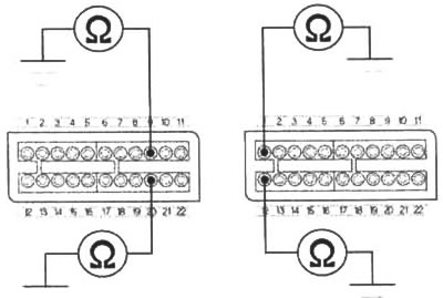
Ground line
Check for continuity between the ECM test harness connector A9 terminal and ground, between the A20 terminal and ground, between the B1 terminal and ground, and between the B12 terminal and ground. There should be continuity at all times.
If there is no continuity, check for an open circuit in the Green/pink wire and Green wire.
Power input line
Turn the ignition switch to "ON" and the engine stop switch to "
Measure the voltage between the ECM test harness connector B6 terminal (+) and ground.
There should be battery voltage.
If there is no voltage, check for an open circuit in the Black/white wire between the ECM and bank angle sensor/relay.
If the wire is OK, check the bank angle sensor/relay (page 5-71).
