Inspection
Remove the seat (page 2-2).
Disconnect the ECM 22P black and 22P gray connectors.

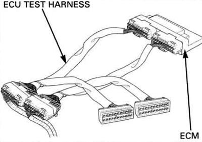
Check the connector for loose or corroded terminals. Connect the ECU test harness between the ECM and main wire harness.
Tool: ECU test harness 07YMZ-0010100 (two required).
1. Input voltage inspection
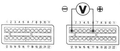
Turn the ignition switch to "ON" and measure and record the input voltage at the test harness terminals using a digital multimeter.
Connection:
- B6 (+) - B1 (-)
- Standard: 4.5 - 5.5 V
If the measurement is out of specification, check the following:
- Loose connection of the ECM multi-connector
- Open circuit in wire harness

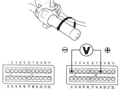
2. Output voltage inspection with throttle fully open
Turn the ignition switch to "ON" and measure and record the output voltage at the test harness terminals.
- Connection: B8 (+) - B1 (-)
- Measuring condition: At throttle fully open

3. Output voltage inspection with throttle fully closed
Turn the ignition switch to "ON" and measure and record the output voltage with the throttle fully closed.

- Connection: B8 (+) - B1 (-)
- Measuring condition: At throttle fully closed
4. Calculate result comparison
Compare the measurement to the result of the following calculation.
With the throttle fully open: Measured input voltage x 0.824 = Vo.
The sensor is normal if the measurement output voltage measured in step 2 is within 10% of Vo.
With the throttle fully closed: Measured input voltage x 0.1 = Vc.
The sensor is normal if the throttle closed output voltage measured in step 3 is within 10% of Vc.
Using an analog meter, check that the needle of the voltmeter swings slowly when the throttle is opened gradually.
Continuity inspection
Open and support the front end of fuel tank (page 3-4).
Disconnect the ECM 22P gray connector and the TP sensor 3P connector.

Check for continuity between the ECM and TP sensor.
If there is no continuity, check for an open or short circuit in the wire harness.
