
User mode
| MALFUNCTION | LCD (DISPLAY) INDICATION | Fl LIGHT INDICATION | INDICATION MODE |
| "NO" | Clock | — | — |
| "YES" | |||
| Engine can start | Clock and "Fl" letters *1 | Fl light turns ON. | Each 2 sec. Clock or "Fl" is indicated. |
| Engine can not start | "Fl" letters *2 | Fl light turns ON and blinks. | "Fl" is indicated continuously. |
*1 When one of the signals is not received by ECM, the fail-safe circuit works and injection is not stopped. In this case, "Fl" and clock are indicated in the LCD panel and motorcycle can run.
*2 The injection signal is stopped, when the crankshaft position sensor signal, tip over sensor signal, #1/#2 ignition signals, #1/#2 injector signals, fuel pump relay signal or ignition switch signal is not sent to ECM. In this case, "Fl" is indicated in the LCD panel. Motorcycle does not run.
"CHEC": The LCD panel indicates "CHEC" when no communication signal from the ECM is received for 3 seconds.
For Example, The ignition switch is turned ON, and the engine stop switch is turned OFF. In this case, the speed-meter does not receive any signal from ECM, and the panel indicates "CHEC".
If CHEC is indicated, the LCD does not indicate the trouble code. It is necessary to check the wiring harness between ECM and speedometer couplers.
The possible cause of this indication is as follows.
Engine stop switch is in OFF position. Side-stand/ignition inter-lock system is not working Ignition fuse is burnt.
Notes:
- Until starting the engine, the Fl light turns ON.
- The Fl light is also turned ON when engine temperature is high or oil pressure is low.
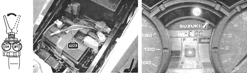
Dealer mode
The defective function is memorized in the computer. Use the special tool's coupler to connect to the dealer mode coupler. (4-20) The memorized malfunction code is displayed on LCD (DISPLAY) panel. Malfunction means that the ECM does not receive signal from the devices. These affected devices are indicated in the code form.
- 09930-82720: Mode select switch
Caution!
- Do not disconnect the ECM lead wire couplers, before checking the malfunction code, or the malfunction code memory is erased and the malfunction code can not be checked.
- Confirm the malfunction code after ignition ON or cranking the engine for few seconds.
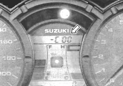
| MALFUNCTION | LCD (DISPLAY) INDICATION | Fl LIGHT INDICATION | INDICATION MODE |
| "NO" | C00 | "Fl" letter turns OFF. | — |
| "YES" | C** code is indicated from small numeral to large one. | For each 2 sec., code is indicated. |
| CODE | MALFUNCTION PART | REMARKS |
| C00 | None | No defective part |
| C12 | Crankshaft position sensor (CKPS) | Pick-up coil signal, signal generator |
| C13 | Intake air pressure sensor (IAPS) | |
| C14 | Throttle position sensor (TPS) | |
| C15 | Engine coolant temperature sensor (ECTS) | |
| C21 | Intake air temperature sensor (IATS) | |
| C23 | Tip over sensor (TOS) | |
| C24 | Ignition signal #1 (IG coil #1) | For#1 cylinder |
| C25 | Ignition signal #2 (IG coil #2) | For #2 cylinder |
| C28 | Secondary throttle valve actuator (STVA) | |
| C29 | Secondary throttle position sensor (STPS) | |
| C31 | Gear position signal (GP switch) | |
| C32 | Fuel injector signal #1 | For#1 cylinder |
| C33 | Fuel injector signal #2 | For #2 cylinder |
| C41 | Fuel pump control system (FP control system) | Fuel pump, Fuel pump relay |
| C42 | Ignition switch signal (IG switch signal) | Anti-theft |
| C44 | Heated oxygen sensor (HO2S) | For E-02, 19 |
| C49 | PAIR control solenoid valve |
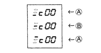
In the LCD (DISPLAY) panel, the malfunction code is indicated from small code to large code.
TPS adjustment
1. Warm up the engine and adjust the engine idle speed to 1300±100 rpm. (2-15)
2. Stop the engine.
3. Connect the special tool (Mode select switch) and select the dealer mode.
4. If the throttle position sensor adjustment is necessary, loosen the screws and turn the throttle position sensor and bring the line to middle.
5. Then, tighten the screw to fix the throttle position sensor.
- TP sensor mounting screw: 3.5 N·m (0.35 kgf·m, 2.5 lb·ft)
- 09930-11950: Torx wrench
- 09930-82720: Mode select switch
(A) Incorrect; (B) Correct position | 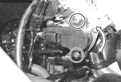 |