
Removal
1. Remove the rider's seat as described on page 17.9.
2. Disconnect and remove the battery as described on page 18.9.
3. Remove the fuel tank as described on page 11.100.
4. Remove both side covers as described on page 17.9.
5. Remove the rear wheel as described on page 16.8.
6. Remove the rear mudguard as described on page 17.12.
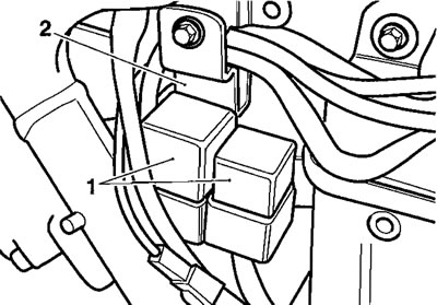
7. From the left hand side, detach the roll over valve from its clip, then release the two screws that secure the relay pack to the airbox side.
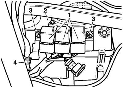
1. Relay pack; 2. Airbox; 3. Screws; 4. Roll-over valve
8. Ease the relay pack from the airbox.
Note: It is not necessary to disconnect or remove the relays or disconnect the rollover valve hoses.
9. If an evaporative canister is fitted, cut the cable ties securing it to the airbox.
10. Make a note of (or mark) the hose locations before disconnecting them from the evaporative canister.

1. Evaporative canister; 2. Hoses; 3. Cable ties
11. Remove the canister.
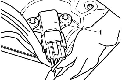
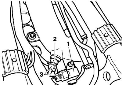
12. Disconnect the electrical connections to the fall detection switch and alternator rectifier.
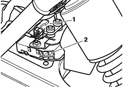
1. Fall detection switch; 2. Alternator rectifier
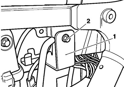
13. Release the fir-tree plugs securing the fuse box to the battery box.
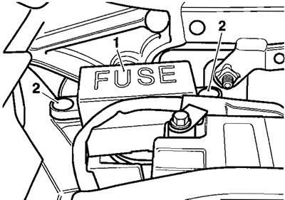
1. Fuse box; 2. Fir-tree plugs
14. Manoeuvre the relay pack, fuse box and other electrical connectors aside.
Note: Before proceeding, make a note of the cable routings around the ECM and ECM bracket.
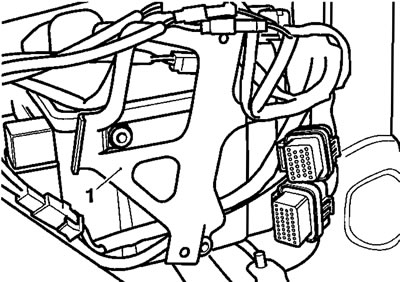
15. Working on the right hand side, remove the screws securing the engine management ECM to its bracket.
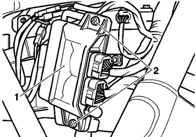
1. ECM; 2. Screws
16. Ease the ECM from its bracket then disconnect the two electrical connections.
Electrical connections
17. Place the ECM to one side.
18. Remove the three screws from the ECM bracket, then detach the bracket.

1. ECM bracket
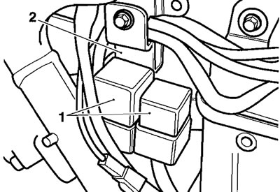
19. Ease the two relay connectors from the battery box by pushing them upwards.
1. Relays; 2. Battery box
20. Disconnect the barometric pressure sensor.
1. Barometric pressure sensor
21. Lay the relays, ECM connectors and other wiring aside.
22. Release the two screws securing the seat lock to the frame, then lay the seat lock (still attached to its cable) to one side.

1. Seat lock; 2. Screws
23. Release the two screws securing the battery box assembly to the frame.
1. Battery box; 2. Screw (left hand shown)
24. Maneouvre the battery box assembly from the motorcycle and place aside.
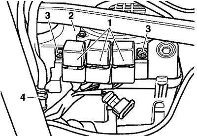
25. Noting their orientation, release the three clips securing the intake plenum to the throttle bodies.
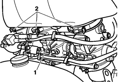
1. Throttle bodies; 2. Clips
26. Noting their orientation, release the two clips securing the intake plenum to the intake duct.

1. Intake plenum; 2. Intake duct; 3. Clips
27. Carefully detach the intake plenum from the throttle bodies and intake duct. Place the intake plenum aside.
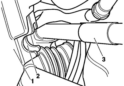
28. Release the clip securing the intake hose to the intake duct.

1. Intake hose; 2. Intake duct; 3. Clip
29. Disconnect the manifold absolute pressure (MAP) and air temperature sensors.
1. MAP sensor; 2. Air temperature sensor; 3. Connectors
Note: Prior to removing the intake duct, the MAP sensor hose must be disconnected.
30. Release the fixing securing the intake duct to its bracket. Remove the duct.

1. Intake duct; 2. Fixing
31. Release the clip securing the intake hose to the airbox.
32. Detach the intake hose and place it aside.
33. Release the clip securing the airbox breather hose to the engine.
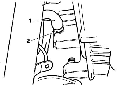
1. Breather hose; 2. Clip
34. Release the two fixings securing the airbox to the frame.

1. Airbox; 2. Fixings
35. Manoeuvre the airbox from the frame.
Installation
1. Position the airbox to the frame ensuring the semi circular feature at the front of the airbox is located on the frame cross tube behind the engine. Attach the airbox breather hose to the engine and secure it with the clip before proceeding.
1. Airbox; 2. Semi-circular feature; 3. Frame cross tube
2. Pivot the airbox upwards at the rear and engage the two bolts that secure it to the frame. Tighten the bolts to 9 Nm,
3. Refit the intake hose to the airbox and secure it with the clip.
Caution! Ensure the hose is positively located to the airbox and is retained by the clip through its full circumference. Rectify if necessary as poor engine performance and engine damage may result from poor hose sealing.
4. Position the intake duct to its bracket and also to the intake hose. Secure the hose with its clip. Tighten the duct fixing to 9 Nm.
Caution! Ensure the hose is positively located to the duct and is retained by the clip through its full circumference. Rectify if necessary as poor engine performance and engine damage may result from poor hose sealing.
5. Reconnect the MAP and air temperature sensors.

1. MAP sensor; 2. Air temperature sensor; 3. Connectors
6. Refit the intake plenum to the throttle bodies and intake duct. Tighten all hose clips.
Caution! Ensure the plenum is positively located to the throttle bodies and intake duct and is retained by the clips through their full circumference. Rectify if necessary as poor engine performance and engine damage may result from poor plenum/duct sealing.
7. Position the battery box to the frame.
8. Tighten the battery box fixings to 9 Nm.
9. Reposition the seat lock to the frame and battery box. Tighten the lock fixings to 5 Nm.
10. On the right hand side, fit the two relays and sockets to their mounting points on the battery box. Ensure that both relays are fully engage on their mountings.
1. Relays; 2. Battery box
11. Arranging the cables to the rear of the ECM bracket as noted prior to removal, refit the ECM bracket and tighten its screws to 3 Nm.
1. ECM bracket; 2. Cables
12. Locate the ECM to its bracket and tighten its screws to 3 Nm.
13. Reconnect both multi-plugs to the ECM.
14. Reconnect the barometric pressure sensor.

Barometric pressure sensor
15. Working on the left hand side, position the relay pack to the airbox.
16. Fit the relay pack screws and tighten to 3 Nm.
1. Relay pack; 2. Airbox; 3. Screws; 4. Roll-over valve
17. Reattach the roll over valve to its bracket.
18. Position the fuse box to the battery box. Retain the fuse box with new fir-tree plugs.
19. Reconnect the fall detection switch and alternator rectifier.
20. If fitted, position and secure the evaporative canister to the airbox using new cable-ties. Reattach the hoses to the canister ensuring they are fitted in the positions noted during stripdown.

1. Evaporative canister; 2. Hoses; 3. Cable ties
21. Refit the rear mudguard as described on page 17.13.
22. Refit the rear wheel as described on page 16.9.
23. Refit and reconnect the battery as described on page 18.10.
24. Refit both side covers as described on page 17.9.
25. Refit the fuel tank as described on page 11.101.
26. Refit the rider's seat as described on page 17.9.