
Rivet link type
The following instructions for the replacement of rivet link type drive chains requires the use of service tool T3880027.
Warning: Before starting work, ensure the motorcycle is stabilised and adequately supported. This will help prevent it from falling and causing injury to the operator or damage to the motorcycle.
1. Support the motorcycle on a stand so the rear wheel is clear of the ground.
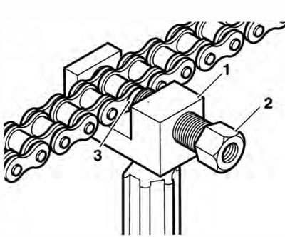
2. Insert the hollow chain cutting tail piece into the tool body so its larger diameter end is facing towards the large pressure screw as shown.
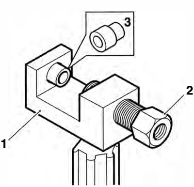
1. TooiT3880027; 2. Large pressure screw; 3. Chain cutting tail piece
3. Position the chain to the tool ensuring that the chain link pin which is to be removed is aligned with the holes in the chain cutting tail piece and the large pressure screw. Tighten the large pressure screw by hand to grip the chain.
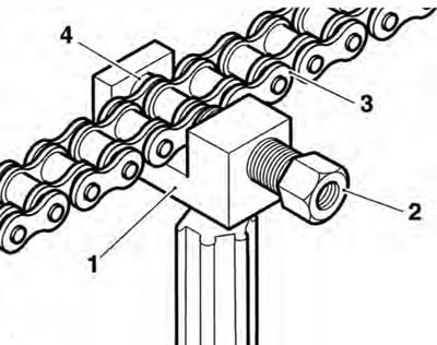
1. Tool T3880027; 2. Large pressure screw; 3. Chain; 4. Chain cutting tail piece
4. Insert the small pressure screw into the larger pressure screw as shown below, until the cutting pin on the small pressure screw contacts the link pin. Ensure that the cutting pin is centralised on the link pin to be removed.
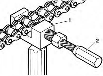
1. Tool T3880027; 2. Small pressure screw
5. Retain the tool body then tighten the small pressure screw until the link pin is pressed out from the chain.
6. Repeat steps 3 to 5 on the remaining chain link pin.
7. Remove the tool and separate the two ends of the chain.
8. Remove the chain cutting tail piece from the body.
Note: The replacement chain is supplied in a split condition, complete with a link kit to join the two ends.
Caution: The component parts of the new link kit are coated with a special grease which must not be removed. Removal of this special grease will severely reduce the service life of the chain.
9. Use the old drive chain to pull the new chain into position as follows: Temporarily attach the end of the new chain to a free end of the old chain using the old connector link. Carefully pull the other end of the old chain to pull the new chain around the sprockets.
Note: Do not use the new connector link as the special grease on it may be removed.
10. Using the new link supplied with the chain kit, join the two ends of the chain. Ensure that the O-rings are positioned as shown below and the link plate is fitted with its markings facing outwards.
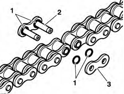
1. O-rings; 2. Link; 3. Link plate
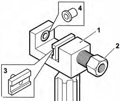
11. Insert the riveting tail piece into the tool body so its larger diameter end is facing towards the large pressure screw as shown.
Note: Tool T3880027 includes two link plate holders, one is for riveted link plates (marked PH5060R), the other is for link plates retained by a spring clip (marked PH4060C). The holder for riveted link plates has a shallow groove to allow for chain link clearance, the holder for clipped link plates has a deep groove to allow for chain link clearance.
12. Insert the link plate holder (marked PH5060R) into the large pressure screw.
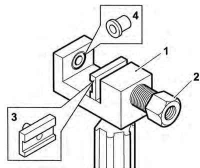
1. Tool body; 2. Large pressure screw; 3. Link plate holder (marked PH5060R); 4. Riveting tail piece
13. Position the tool to the chain. Ensure the link plate holder is correctly located in the large pressure screw.
1. Tool body; 2. Large pressure lever; 3. Link plate holder (marked PH 5060R); 4. Riveting tail piece
14. Locate the split link pins such that the pins will enter the groove in the link plate holder when the link plate is pressed on to the link.
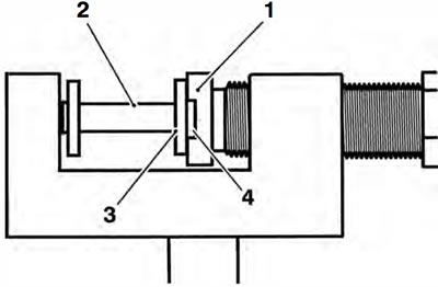
1. Link plate holder; 2. Link plate; 3. Chain link; 4. Link plate holder groove
15. Retain the tool body and tighten the large pressure screw until the link plate is pressed fully onto the link.
16. Back off the pressure screw, slide the tool assembly to one side and check that the split link is correctly assembled.
17. Remove the link plate holder from the tool. Do not remove the riveting tail piece from the tool.
18. Insert the flare pin into the large pressure screw.
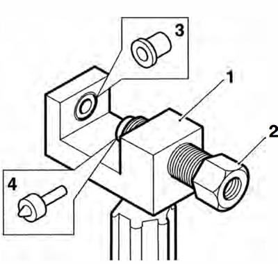
1. Tool body; 2. Large pressure screw; 3. Riveting tail piece; 4. Riair pin
19. Locate one of the split link pins into the riveting tail piece and screw the large pressure screw in until the flare pin contacts the split link end. Ensure the split link pin is centrally located on the flare pin.
20. Retain the tool body and tighten the large pressure screw until the split link end is riveted-over.
1. Tool body; 2. Large pressure screw; 3. Flare pin
21. Back off the large pressure screw and rivet the remaining split link pin as described above.
22. Remove the tool from the chain and check that both the split link pins are correctly riveted as shown below.
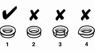
1. Correct riveting; 2. Insufficient riveting; 3. Excessive riveting; 4. Riveting off-centre
Warning: If either split link pin is not correctly riveted, the split link must be removed and replaced with a new link. Never operate the motorcycle with an incorrectly riveted split link as the link could fail resulting in an unsafe riding condition leading to loss of control and an accident.