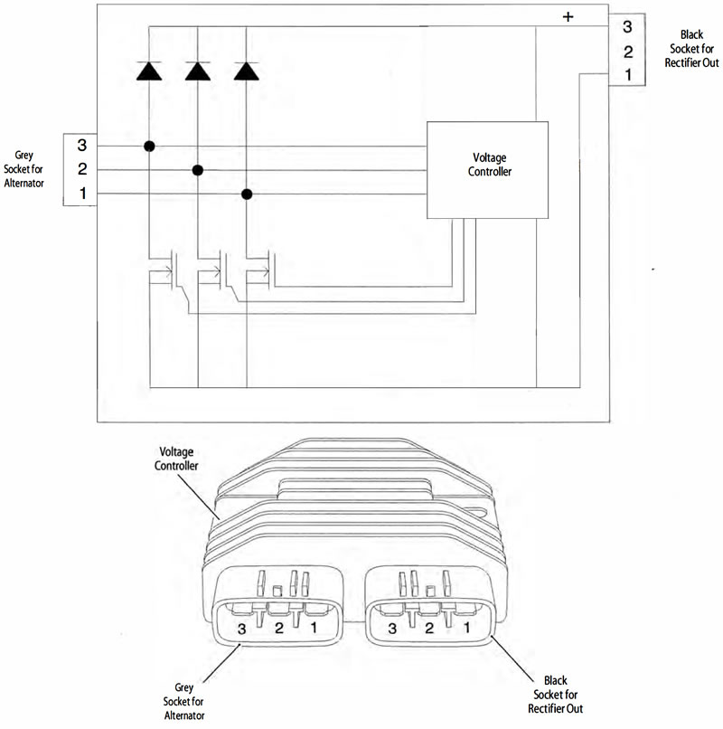
As the voltage of the AC signal from the generator rises, the voltage controller switches the FETs to avoid over voltage on the output.
The diodes and FETs can be checked using a multimeter on DIODE setting. Disconnect the two electrical connectors from the rectifier/regulator and check the readings as indicated below.
Note: This test does not check for voltage regulation.
| Fault | Possible cause | Action |
| Battery not charging | Fuse 11 | Check the condition of fuse 11: |
| Battery | Check the condition of the battery. Test the battery using the BatteryMate 150-9. Refer to the instructions supplied with the BatteryMate 150-9. Ensure the battery is serviceable: | |
| Rectifier/Regulator | Disconnect the black and the grey connectors from the rectifier/ regulator and proceed to pinpoint test 1: | |
| Alternator | Test the alternator stator (see page 17-22) |
Pinpoint Tests
| Test | Result | Action |
| 1. Check diodes forward bias: Positive (+) probe to rectifier black socket pin 1 to: Negative (-) probe to rectifier grey socket pin 1 Negative (-) probe to rectifier grey socket pin 2 Negative (-) probe to rectifier grey socket pin 3 | 0.4V to 0.7V | Proceed to test 2 |
| Open circuit or short circuit | Replace the unit. Proceed to test 4 | |
| 2. Check FET function forward bias: Negative (-) probe to rectifier black socket pin 3 to: Positive (+) probe to rectifier grey socket pin 1 Positive (+) probe to rectifier grey socket pin 2 Positive (+) probe to rectifier grey socket pin 3 | 0.1 V to 0.3 V | Proceed to test 3 |
| Open circuit or short circuit | Replace the unit. Proceed to test 4 | |
| 3. Check diodes reverse bias: Negative (-) probe to rectifier black socket pin 1 to: Positive (+) probe to rectifier grey socket pin 1 Positive (+) probe to rectifier grey socket pin 2 Positive (+) probe to rectifier grey socket pin 3 Positive (+) probe to rectifier black socket pin 3 to: Negative (-) probe to rectifier grey socket pin 1 Negative (-) probe to rectifier grey socket pin 2 Negative (-) probe to rectifier grey socket pin 3 | More than 1.4 V or 0 V on meter | Proceed to test 4 |
| Less than 1.4 V or short circuit | Replace the unit. Proceed to test 4 | |
| 4. Reconnect the harness and run the engine. Check the charging Voltage at 2,000 rpm: | 13-15 V | Action complete - quit test |
| Fault still present | Test alternator stator (see page 17-22) | |
| If alternator stator is serviceable, contact Triumph service |
Circuit Diagram