
The alternator rectifier is located under the head stock, behind the radiator. To access the rectifier, remove the radiator (see page 10-91).
The stator is an assembly of 18 coils, arranged into three phases. It is possible to check for continuity and short circuits through the coils and to earth.
Note:
- Only repair the stator harness between the rectifier and where the harness goes into the crankcase.
- Do not attempt to repair the stator coils.
- If the battery is not fully charged, the charging voltage may be lower than specified when checking at 2,000 rpm.
- Ensure all additional accessories (auxiliary lights, heated grips etc.) are switched off.
| Fault | Possible cause | Action |
| Battery not charging | Battery | Check the condition of the battery. Test the battery using the BatteryMate 150-9. Refer to the instructions supplied with the BatteryMate 150-9. Ensure the battery is serviceable: |
| Alternator | Proceed to pinpoint test 1: | |
| Rectifier/Regulator | Test the rectifier/regulator (see page 17-24) |
Pinpoint Tests
| Test | Result | Action |
| 1. Check cable and terminal integrity: Battery positive (+) Battery negative (-) Rectifier/regulator black connector pin 1 Rectifier/regulator black connector pin 3 Rectifier/regulator grey connector pin 1 Rectifier/regulator grey connector pin 2 Rectifier/regulator grey connector pin 3 | OK | Disconnect the battery leads, negative (black) lead first. Disconnect rectifier/regulator black connector and proceed to test 2 |
| Faulty | Rectify fault, proceed to test 4 | |
| 2. Check cable continuity Rectifier/regulator black connector pin 1 to battery lead negative connector Rectifier/regulator black connector pin 3 to battery lead positive connector | OK | Reconnect the battery leads, positive (red) lead first. Reconnect the rectifier/regulator black connector. Disconnect the rectifier/regulator grey connector and proceed to test 3 |
| Open circuit | Locate and rectify wiring fault, proceed to test 4 | |
| 3. Check resistance through the coils: Alternator pin 1 to pin 2 Alternator pin 2 to pin 3 Alternator pin 3 to pin 1 | 0.14Ω to 0.18Ω | Proceed to test 4 |
| Open circuit or short circuit | If the fault is between the rectifier and the crankcase, repair the harness. Proceed to test 4 If the fault is after the crankcase, replace the unit. Proceed to test 5 | |
| 4. Reconnect the harness and run the engine. Check the charging Voltage at 2,000 rpm: | 13.5-15V | Action complete - quit test |
| Fault still present | Disconnect the rectifier/regulator grey connector and proceed to test 5 | |
| 5. Check the alternator AC output Voltage at 850 rpm by probing the 3-pin stator connector as follows: Positive (+) probe to pin 1 negative (-) probe to pin 2 Positive (+) probe to pin 2 negative (-) probe to pin 3 Positive (+) probe to pin 3 negative (-) probe to pin 1 | 15 V AC to 25 V AC | Test rectifier/regulator (see page 17-24) |
| Less than 15 V AC | Replace unit. Proceed to test 6 | |
| 6. Reconnect the harness and run the engine. Check the charging Voltage at 2,000 rpm: | 13.5-15V | Action complete - quit test |
| Fault still present | Contact Triumph service |
Circuit Diagram
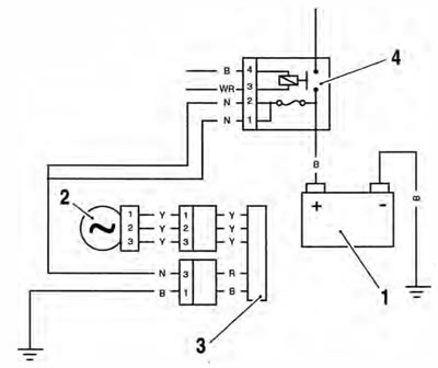
1. Battery; 2. Alternator; 3. Rectifier/Regulator; 4. Starter relay