
Removal
- 1. Remove the camshaft drive chain tensioner (see page 3-8).
Note:
- It is not necessary to remove the camshaft drive chain completely.
- Each camshaft and sprocket is removed as an assembly.
- Before commencing work, ensure the crankshaft 'dot' mark is in alignment with the line in the crankcase.
- 2. Note the orientation of the camshaft ladder in relation to the head.
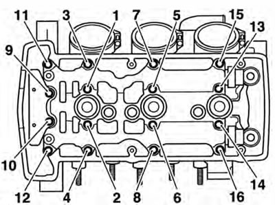
- 3. Progressively release the bolts securing the camshaft ladder to the head in the sequence shown below.
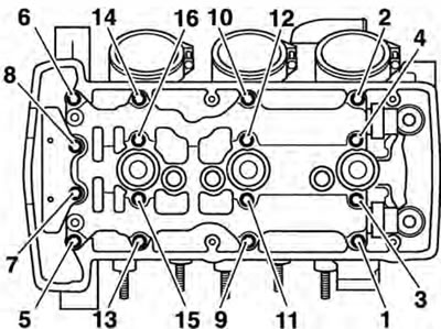
Camshaft Ladder Bolt Release Sequence
- 4. Remove the camshaft ladder and top pad, and collect the dowels (if loose) and spark plug tower O-rings.
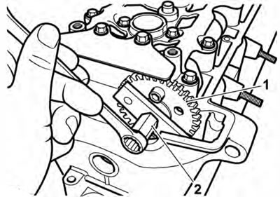
- 5. Lift the camshaft drive chain from the exhaust camshaft sprocket and remove the exhaust camshaft.
- 6. Repeat the procedure for the inlet camshaft.
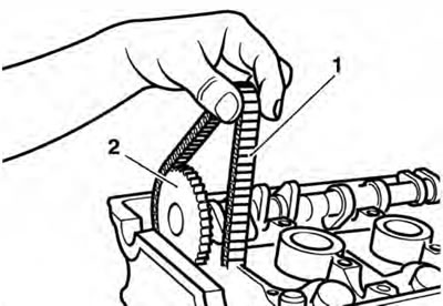
1. Camshaft drive chain; 2. Inlet camshaft
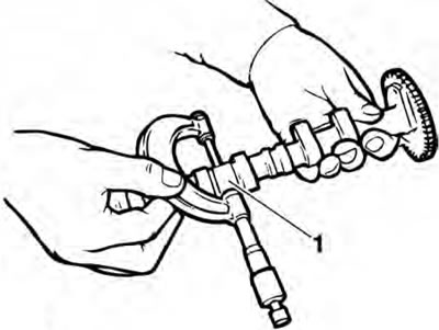
Note: The inlet and exhaust camshafts are different. They can be identified by a raised feature in the centre of the exhaust camshaft, which is machined off on the inlet camshaft. The camshafts can be further identified a letter 'I' for inlet or 'E' for exhaust stamped on the end of the sprocket boss.
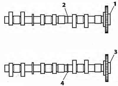
1. Inlet camshaft; 2. Machined section; 3. Exhaust camshaft; 4. Raised section
Camshaft and Bearing Cap Inspection
- 1. Inspect the camshaft sprockets for damaged and worn teeth. Replace as necessary.
Caution:
- The same sprocket is used for both inlet and exhaust camshafts. To attach the ' sprocket to the different camshafts, different bolt holes are used.
- Never fit a camshaft sprocket to a camshaft using incorrectly identified bolt holes. Severe engine damage will result from incorrect attachment.
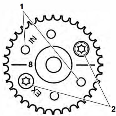
1. Inlet camshaft bolt holes; 2. Exhaust camshaft bolt holes
Standard Journal Diameters
Standard: 23.940 - 23.960 mm
1. Standard journal
3. Examine the camshaft and camshaft ladder for excessive wear and damage.
- 4. Check the journal-to-head clearances, using 'Piastigage' (Triumph part number 3880150-T0301) as follows:
- a) Ensuring that the camshaft sprocket alignment marking is located as for removal, assemble one camshaft to the head and progressively tighten the camshaft ladder in the sequence shown overleaf (see page 3-15).
- b) Remove the camshaft ladder using the bolt release sequence given earlier. Wipe the exposed areas of both the camshaft journal and a single cap area of the ladder.
- c) Apply a thin smear of grease to the journal and a small quantity of silicone release agent to the camshaft cap area of the ladder.
- d) Size a length of the Plastigage to fit across the camshaft journal. Fit the Plastigage to the camshaft journal using the grease to hold the strip in place.
- e) Refit the camshaft ladder then evenly and progressively tighten all the camshaft ladder bolts in the correct sequence (see camshaft installation). Release the bolts and remove the camshaft ladder.
Using the gauge provided with the Plastigage kit, measure the width of the now compressed Plastigage.
Note: The camshaft ladder is unique to each cylinder head and is, therefore, not available individually. If the camshaft ladder is worn or damaged, the complete cylinder head must be replaced.
Measuring the Compressed Plastigage.
- 5. Calculate the journal clearance 'Gsing the Plastigage chart supplied with the Plastigage kit.
Camshaft journal clearance
Standard: 0.040 - 0.081 mm
Service limit: 0.170 mm
- 6. If the clearance measured is within the specified tolerance, remove the ladder and clean off all traces of Plastigage. Assemble the camshafts (see page 3-15).
Note: If the measured clearance is outside the tolerance, and the camshaft journals are within tolerance, the cylinder head must be replaced.
Caution: Although Plastigage is oil soluble, all traces of the material must be removed to prevent blockage of the oil drillings and resultant engine damage.
Installation
- 1. Thoroughly clean the camshafts and journals. Inspect the ends of the camshafts for correct fitment of the sealing plugs. Lubricate the camshafts with clean engine oil before fitting to the head.
- 2. Locate each camshaft to the head ensuring the camshafts are correctly identified (inlet and exhaus and are also correctly located over their respective valve banks.
- 3. Working on one camshaft at a time, locate the camshaft drive chain over the camshaft sprocket. Position the camshaft in the same position as for removal before attempting to fit the ladder (that is, with the timing marks on the camshaft sprockets level and pointing inwards, and with the 'dot' mark on the primary gear in alignment with the line on the crankcase).
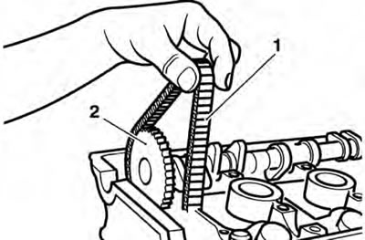
1. Camshaft drive chain; 2. Inlet camshaft
- 4. Repeat the procedure for the other camshaft.
Caution: If the camshafts and ladder are fitted without first aligning the timing marks on both the crankshaft and camshaft sprockets, the inlet and exhaust valves will contact each other causing damage to both the head and the valves.
- 5. Lubricate the camshaft bearing areas of the camshaft ladder with a 50/50 solution of engine oil and molybdenum disulphide grease.
- 6. Assemble the dowels, camshaft ladder and top pad in the same location and orientation as prior to removal.
Note: The bolts for the camshaft cap ladder are tightened in stages.
Stage 1
- 7. Lubricate the threads of the camshaft cap ladder bolts with clean engine oil, then. fit and evenly tighten the bolts to 5 Nm, in the sequence shown below.
Camshaft Cap Ladder Bolt Tightening Sequence
Stage 2
- 8. In the sequence shown above, tighten the bolts to 10 Nm.
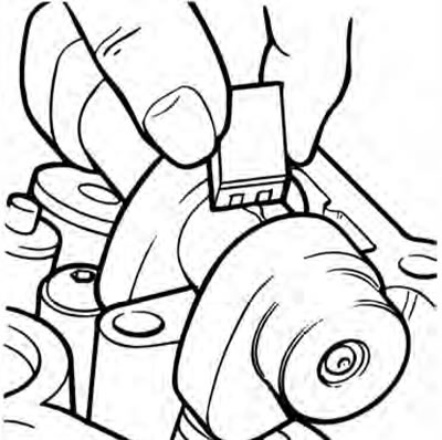
- 9. Before fitting the camshaft drive chain tensioner, ensure that each camshaft rotates freely using service tool T3880102. Do not rotate either camshaft by more than 5°.
1. Exhaust camshaft; 2. Tool T3880102
Caution: If any components have been renewed, the valve clearances must be checked and adjusted. Running with incorrectly adjusted valve clearances may cause excess engine noise, rough running and engine damage.
- 10. Refit the camshaft drive chain tensioner (see page 3-9).
- 11. Rotate the engine through 4 full revolutions, and reset number 1 cylinder to TDC. Ensure that the 'got' mark on the primary gear aligns with the line on the crankcase.
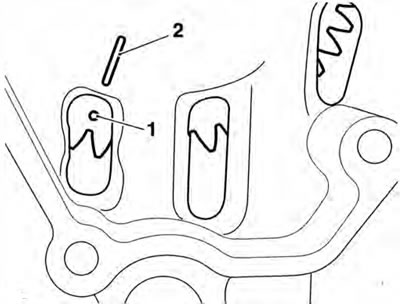
1. 'Dot' mark; 2. Marker line
Note: In addition to the 'dot' mark alignment, at TDC, the alignment marks on the camshaft sprockets will point inwards at a point level with the joint face.
- 12. Check that the camshaft timing marks align as illustrated below. Rectify any misalignment before proceeding.
Note: The Tiger 800 and Tiger 800XC camshaft sprockets are common to Daytona 675 and Street Triple models, but use different timing marks. The timing marks for Tiger 800 and Tiger 800 XC are identified by the number 8 next to the timing mark.
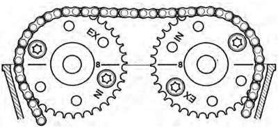
Camshaft to Cylinder Head Alignment Marks
- 13. Check the valve clearances. Adjust as necessary (see page 3-18).