
Caution: The upper and lower crankcases are machined as a matched set and must never be assembled to nonmatching halves. Doing so may cause seizure of the engine.
1. Remove the engine from the frame (see page 9-3).
2. Remove the sump (see page 8-15).
3. Remove the engine covers (see pages 3-8, 4-6 and 7-21).
4. Remove the clutch (see page 4-6).
5. Remove the oil pump (see page 8-8).
Disassembly
Caution: Failure to follow the correct screw release sequence may result in permanent crankcase damage.
1. Invert the engine to give access to the lower crankcase bolts.
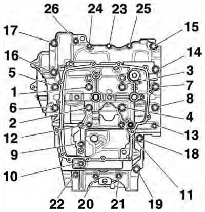
2. Release the lower crankcase bolts in the sequence shown in the diagram below. Note the position of the hardened washers under bolts 19 to 26.
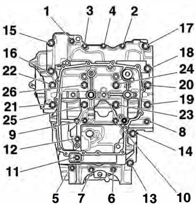
Crankcase Bolt Release Sequence
3. Separate the lower and upper crankcases ensuring that the 3 locating dowels remain in the upper crankcase.
Caution: Do not use levers to separate the upper and lower sections of the crankcase or damage to the crankcases could result.
Note: At this point the transmission shafts, balancer, crankshaft, bearings etc. can be removed.
Note:
- The position of each individual bearing shell prior to removal.
- Collect the piston cooling jets from below the upper main bearings, noting that the piston cooling jet for number 3 cylinder is longer and has a larger diameter drilling than the piston cooling jets for number 1 and 2 cylinders. lt can also be identified by its smaller outside diameter and a groove around its circumference.
Assembly
1. Use high flash-point solvent to clean the crankcase mating faces. Wipe the surfaces clean with a lint-free cloth.
2. Fit the gearbox shafts (if removed), ensuring the locating ring and dowels on the output shaft bearings are positioned correctly in the crankcase.
3. Ensure that the transmission is in neutral.
4. Ensure that the 3 locating dowels are in position in the upper crankcase.
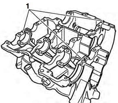
1. Locating dowels
5. Apply a thin bead of silicone sealant (At the factory, ThreeBond 1215 is used) to the lower crankcase mating faces.
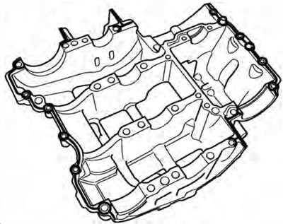
Sealer areas
Caution: Do not use excessive amounts of sealer. The extra sealer may become dislodged and could block the oil passages in the crankcases causing severe engine damage.
6. If removed, insert the three piston cooling jets into the main bearing housings in the upper crankcase.
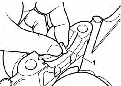
1. Piston cooling jet
Caution: Ensure the three piston cooling jets are installed. If the piston cooling jets are omitted, oil pressure will be reduced. Running the engine with low oil pressure will cause severe engine damage.
Note: The piston cooling iet for number 3 cylinder is longer and has a larger diameter drilling than the piston cooling iets for number 1 and 2 cylinders. lt can also be identified by its smaller outside diameter and a groove around its circumference. Piston cooling iets must not be installed incorrectly.
7. Install and lubricate the crankshaft bearing shells with clean engine oil (see bearing selection on page 5-12 before proceeding)
8. Lubricate the crankshaft journals with clean engine oil.
9. Position the lower crankcase to the upper. An assistant may be required to support the crankcase during alignment.
10. Fit the screws into the lower crankcase and hand tighten until the bolt heads are near contact with the crankcase. Note the position of the hardened washers under bolts 1 to 8.
Note: The crankcase screws are tightened in stages. Two different sizes of crankcase screw are used. All screws are tightened through the first stage of the tightening procedure but only the MS size screws are tightened at the second stage.
Caution: Failure to follow the correct screw tightening sequence may result in permanent crankcase damage.
Stage 1 - all screws
1. In the sequence shown below, tighten all crankcase screws to 12 Nm.
Crankcase Bolt Tightening Sequence
Stage 2 - MS screws only
1. In the correct sequence, tighten only the M8 size crankcase screws (numbers 1 to 8) to 22 Nm.
2. In the correct sequence, tighten only the M8 size crankcase screws (number 9 to 14) to 22 Nm.
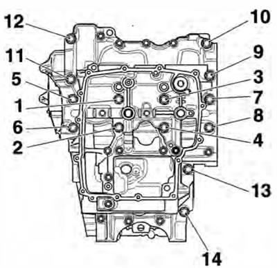
MS Crankcase Bolt Tightening Sequence
3. Rotate the crankshaft clockwise. Check for tight spots and rectify as necessary.
4. Refit the oil pump (see page 8-13).
5. Refit the clutch (see page 4-10).
6. Refit the engine covers (see pages 3-11, 4-12 and 7-22).
7. Refit the sump (see page 8-16).
8. Install the engine in the frame (see page 9-5).