
Removal
Connecting rods may be removed from the engine after first removing it from the frame. The cylinder head must be removed and the crankcase halves separated.
1. Mark each big end cap and connecting rod to identify both items as a matched pair and to identify the correct orientation of the bearing cap to the connecting rod.
2. Release the connecting rod bolts and remove the big end cap. Ensure that the bearing shell remains in place in the cap.
1. Big end cap; 2. Connecting rod bolt
Note: It may be necessary to gently tap the big end cap with a rubber mallet to release the cap.
3. Push the connecting rod up through the crankcase and collect the piston and connecting rod from the top.
4. Label the assembly to identify the cylinder from which it was removed.
Caution: Never re-use connecting rod bolts. If the connecting rod cap is disturbed, always renew the bolts. Using the original bolts may lead to severe engine damage.
5. Remove the liner using tool T3880101 (see page 5-17).
6. Detach the piston from the connecting rod (see page 5-13).
Installation
Note:
- Connecting rod bolts are treated with an anti-rust solution which must not be removed.
- Clean the connecting rod with high flashpoint solvent.
- Remove all bearings and inspect for damage, wear and any signs of deterioration and replace as necessary.
Warning: Connecting rod bolts MUST only be used once. If the bolts are removed or undone for any reason, new bolts MUST always be used. Re-using bolts can cause connecting rods and their caps to detach from the crankshaft causing severe engine damage, loss of motorcycle control and an accident.
Note:
- Ensure the piston is fitted correctly to the connecting rod.
- If a previously run engine is being rebuilt, always ensure that the piston and con-rod are assembled in the same orientation, and to the same cylinder, as prior to strip-down.
1. Fit the piston onto the connecting rod (see page 5-15).
2. Apply silicone sealer to the liner-to-crankcase mating face (At the factory, Three Bond 1215 is used).
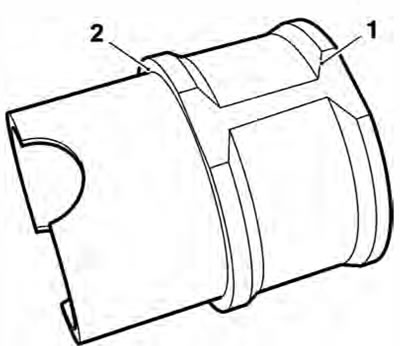
1. Liner; 2. Sealer area
3. Fit the piston and connecting rod assembly into the liner from the bottom.
4. Fit the liner into the crankcase ensuring that the arrow on the piston faces forward.
5. The liners must be positioned such they do not touch each other - it must be possible to pass a 0.1 mm feeler gauge between the centre liner and its adjacent liner on either side. If the liners touch at any point, rotate the liners until there is a minimum 0.1 mm clearance.
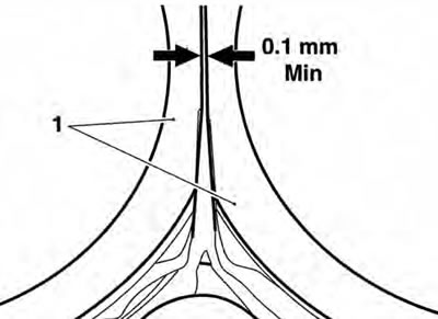
1. Liners
Note: Ensure that the piston/liner/connecting rod assembly aligns correctly with the crankshaft journal during assembly into the crankcase.
6. Select the big end bearing shells (see page 5-10).
7. Fit the bearing shells to the connecting rod and big end cap and lubricate with a 50/50 solution of engine oil and molybdenum disulphide grease.
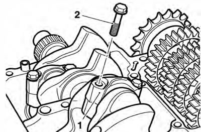
8. Align the connecting rod to the crankshaft and fit the big end cap.
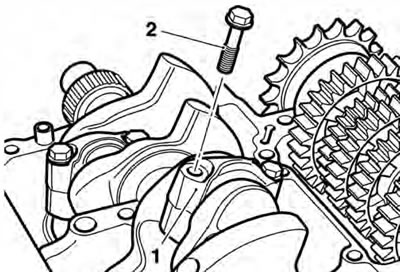
1. Big end cap; 2. Connecting rod bolt
Caution: The torque characteristics of the connecting rod bolts are sensitive to the correct lubrication being applied. If the threads and under head areas are not lubricated with molydenum disuplhide grease, the bolts may be stretched and may become loose when in service resulting in an expensive engine failure.
9. Lubricate the threads and under-head area of the new bolts with molybdenum disulphide grease. Tighten the bolts evenly and progressively in five stages as follows:
Caution: The torque characteristics of the connecting rod bolts are sensitive to the rate at which they are tightened. If all the torque is applied in one action, the bolt may be stretched and may become loose when in service resulting in an expensive engine failure.
- a) tighten to 22 Nm;
- b) release 120°;
- c) tighten to 10 Nm;
- d) tighten to 14 Nm;
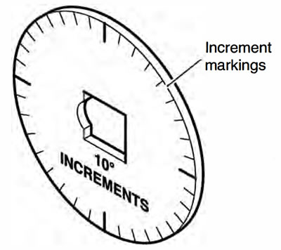
- e) tighten through 120° of bolt rotation as measured using the Triumph torque turn gauge 3880105-T0301.
Serviice Tool 3880105-T0301