
Removal
1. Remove the alternator rotor from the crankshaft (see page 17-19).
2. Separate the two halves of the crankcase (see page 5-4).
3. Remove the connecting rods (see page 5-8).
4. Remove the camshaft drive chain (see page 3-18).
5. Release and remove the crankshaft from the upper crankcase.
Note:
- Identify the location of each bearing shell.
- Remove all bearings and inspect for damage, wear, overheating (blueing) and any other signs of deterioration. Replace the bearings as a set if necessary.
- Collect the piston jets from below the upper main bearings.
- If the camshaft drive chain sprocket is removed from the crankshaft for any reason, always install a new fixing. Tighten to 27 Nm.
6. Remove the balancer (see page 6-3).
Installation
Caution: Always check the bearing journal clearance (see page 5-12), before final assembly of the crankshaft. Failure to correctly select crankshaft bearings will result in severe engine damage.
1. If removed, insert the three piston cooling jets into the main bearing housings in the upper crankcase.
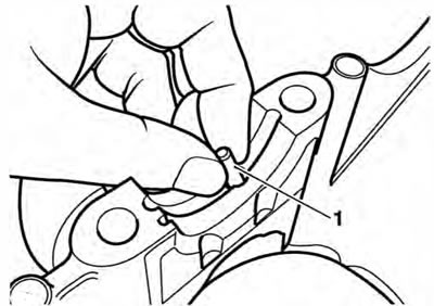
1. Piston cooling jet
Caution: Ensure the three piston cooling jets are installed. If the piston cooling jets are omitted, oil pressure will be reduced. Running the engine with low oil pressure will cause severe engine damage.
Note: The piston cooling jet for number 3 cylinder is longer and has a larger diameter drilling than the piston cooling jets for number 1 and 2 cylinders. lt can also be identified by its smaller outside diameter and a groove around its circumference. Piston cooling jets cannot be installed incorrectly.
2. Select and fit new main and big end shell bearings (see page 5-12).
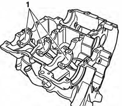
1. Big end shells
3. Lubricate all bearings with a 50150 solution of engine oil and molybdenum disulphide grease.
4. Ensure that the crankshaft is clean, and that the oilways within the crank are clean and free from blockages and debris.
5. Refit the balancer (see page 6-4).
6. Install the crankshaft ensuring that the crank pins align with the big ends and that the crankshaft and balancer gear markings align as shown in the next illustration.
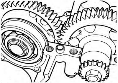
1. Balancer backlash and drive gear markings; 2. Crankshaft markings
7. Refit the connecting rods (see page 5-8).
8. If removed, refit the transmission shafts.
9. Assemble the crankcases (see page 5-4).
10. Assemble the alternator rotor (see page 17-20).
11. Refit the camshaft drive chain (see page 3-20).