
Removal
1. Remove the engine from the frame (see page 9-3).
2. Separate the two halves of the crankcase (see page 5-4).
3. Remove the output shaft from the crankcase (see page 7-10).
4. Remove the selector shaft (see page 7-6).
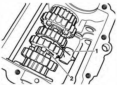
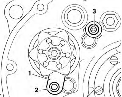
5. Remove and discard the two selector fork shaft retaining fixings, noting the position of the washer and the selector drum keeper plate.
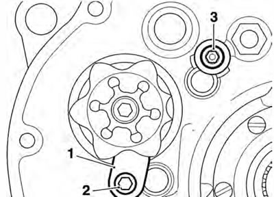
1. Selector drum keeper plate; 2. Output selector fork shaft fixing; 3. Input selector fork shaft fixing and washer
Caution: The two output shaft selector forks incorrectly. Ensure the position and orientation of the selector forks are marked prior to removal. Incorrect fitting of the selector forks will cause gearbox damage.
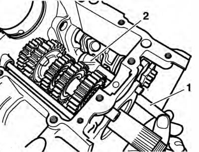
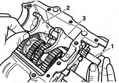
6. Noting the positions of the selector forks, slide the output selector shaft from the crankcase in the direction of the clutch. Collect the two selector forks as they are released by the selector fork shaft.
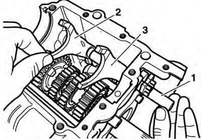
1. Output selector shaft; 2. Sixth gear selector fork; 3. Fifth gear selector fork
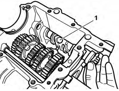
7. Noting the position of the selector fork, remove the input selector shaft, leaving the selector fork in the gearbox.
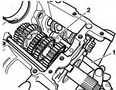
1. Input selector shaft; 2. Selector fork
8. Remove the gear position sensor.
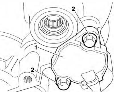
1. Gear position sensor; 2. Fixings
9. Wihdraw the selector drum from within the crankcase.
1. Selector drum removal
10. Collect the input shaft selector fork from the crankcase.
Inspection
1. Examine all components for damage and/or wear, paying particular attention to the selector forks and selector drum. Replace any parts that are damaged and/or worn.
Gear selector fork thickness
- Standard: 5.90 - 6.00 mm
- Service limit: 5.80 mm
Gear selector groove width
- Standard: 6.10-6.17 mm
- Service limit: 6.27 mm
Selector fork to groove clearance
- Service limit: 0.47 mm max
2. Examine the gear change shaft seal for damage and/or wear. Replace the seal if damaged and/or worn.
Installation
1. Position the input shaft selector fork into the crankcase, locating the forks into the selector groove on the input shaft. Ensure the fork is fitted in the position noted during removal.
1. Input shaft selector fork; 2. Input shaft
2. Using clean engine oil, lubricate the selector drum bearings. Lubricate the selector drum tracks with a 50150 solution of engine oil and molybdenum disulphide grease.
3. Position the selector drum into the crankcase.
1. Selector drum
4. Refit the gear position sensor, ensuring the pin on the sensor engages in the hole selector drum. Tighten the fixings to 5 Nm.
5. Rotate the selector drum and ensure a smooth movement. Rectify as necessary.
Caution: The selector forks can be fitted incorrectly. Ensure the position and orientation of the selector forks are the same as noted during removal. Incorrect fitting of the selector forks will cause gearbox damage.
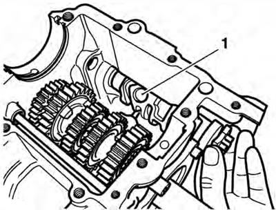
6. Push the input selector shaft into the crankcase from the clutch end. As the shaft is inserted locate the selector fork onto the shaft. Ensure the fork is fitted in the position noted during removal, and the pin on the fork engages in the track in the drum.
1. Input selector shaft; 2. Selector fork
7. Push the output selector shaft into the crankcase from the clutch end. As the shaft is inserted, locate the selector forks. Ensure the fork is fitted in the position noted during removal, and the pin on the fork engages in the track in the drum.
1. Output selector shaft; 2. Sixth gear selector fork; 3. Fifth gear selector fork
8. Fit two new selector shaft retaining fixings, ensuring the washer and the selector drum keeper plate are fitted in the positions noted during removal. Tighten the fixings to 12 Nm.
1. Selector drum/shaft keeper plate; 2. Fixing; 3. Input selector shaft fixing and washer
9. Refit the selector shaft (see page 7-6).
10. Refit the output shaft (see page 7-11).
11. Assemble the two halves of the crankcase (see page 5-4).
12. Refit the engine to the frame (see page 9-5).