
Removal
Warning: Before starting work, ensure the motorcycle is stabilised and adequately supported. This will help prevent it from falling and causing injury to the operator or damage to the motorcycle.
1. Raise and support the motorcycle.
2. Remove the rider's seat (see page 16-13).
3. Disconnect the battery, negative (black) lead first and remove the battery (see page 17-8).
4. Remove the fuel tank (see page 10-91).
5. Remove the airbox (see page 10-98).
6. Remove the throttle bodies (see page 10-107).
7. Drain the engine oil (see page 8-7).
8. Drain the coolant (see page 11-5).
9. Remove the radiator (see page 11-4).
Note: Secure the coolant hoses to prevent damage as the engine is removed.
10. Temporarily remove the sump guard (see page 16-24).
11. Remove the exhaust system completely (see page 10-118).
12. Refit the sump guard (see page 16-21).
13. Support the engine on proprietary lifting jacks, at the front and rear. Position the jacks under the sump guard, directly under the four fixings.
14. Secure the engine to the jacks, using suitable straps, to prevent it from moving or falling as the frame is removed.
15. Disconnect the gearchange linkage at the gearbox shaft.
16. Remove the sprocket cover.
Caution: To prevent chain damage, do not allow the chain to come into contact with dirt, road grit etc.
17. Set the drive chain adjustment to allow maximum free play in the chain (see page 12-8).
18. Remove the swinging arm (see page 12-13).
19. Detach the drive chain from the front sprocket and remove it.
20. Noting their routing, disconnect the electrical connections from the main harness to the engine.
21. Remove the bolt and detach the engine earth cables from the rear of the crankcase. Note the order of the earth terminals on the bolt before removal.
22. Remove the bolt and detach the engine starter cable from the starter motor.
23. Slacken the cable locknut and release the adjuster at the clutch cover end to give maximum play in the cable.
24. Release the clutch cable from the actuating arm by pushing the inner cable nipple through the arm and sliding the cable out of the slot. Detach the cable from the bracket.
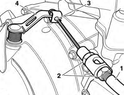
1. Clutch cable; 2. Adjuster; 3. Inner cable nipple; 4. Actuating arm
25. Remove the front wheel (see page 15-10).
26. Ensure that the engine is still adequately and securely supported.
27. Support the frame centrally using suitable lifting equipment. The frame is fitted with two different mounting conditions at the rear lower gearbox mounting bolt. Either of these conditions may be found on any motorcycle from the start of production. These consist of either of the following:
- the frame is fitted with a conventional adjuster sleeve, located on the left hand side of the frame;
- the frame is fitted with a shim (available in varying thicknesses) located between the crankcase and the engine mounting boss. This arrangement is also fitted with a spacer plate, permanently fitted to the crankcase. A frame adjuster sleeve is fitted to the frame, however this is fitted from the outside of the frame (so that the adjuster slots are inside the frame). This sleeve is not used for frame adjustment; it is only for bolt location purposes.
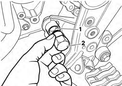
28. Noting the mounting arrangement described above, release the nut securing the rear lower gearbox mounting bolt. Collect the hardened washer from under the nut.
29. Remove the bolt.
Models Fitted with a Frame Adjustment Shim
1. Collect and retain the shim.
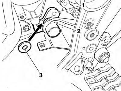
1. Crankcase plate; 2. Frame boss; 3. Shim
Models Fitted with a Frame Adjuster Sleeve
1. Using tool T3880166 loosen the frame adjuster and unscrew it fully to allow clearance between the frame and engine.
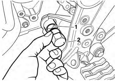
1. Rear lower frame adjuster sleeve; 2. Tool T3880166
All Models:
1. Note the position of the two spacers installed to the two cylinder head bolts, on the left hand side of the engine.
2. Remove the rear cylinder head mounting bolts. Collect the spacer from between the left hand mounting and the frame.
3. Remove the front cylinder head mounting bolts. Collect the spacer from between the left hand mounting and the frame, and the washer from under the right hand bolt head.
Caution: Damage to painted surfaces, such as the frame, cylinder head or crankcases, could result from inadequate care during this process.
4. Carefully lower the frame at the front and raise it at the rear until the rear lower mount clears the crankcase.
5. Carefully lift the frame from the engine in an upwards direction, ensuring the front cylinder head mounts are clear of the cylinder head, and the rear mounting is clear of the crankcase.
Installation
1. Support the engine on proprietary lifting jacks, at the front and rear. Position the jacks under the sump guard, directly under the four fixings.
2. Secure the engine to the jacks, using suitable straps, to prevent it from moving or falling as the frame is installed.
3. Carefully lower the frame over the engine, front first so the front mountings pass under the cylinder head mountings. Lower the rear of the frame until the rear cylinder head mountings align. Fit the right hand bolt, but do not tighten at this stage.
4. Fit the spacer to the left hand rear cylinder head mounting as noted during removal. Fit the left hand bolt, but do not tighten at this stage.
5. Lower the rear of the frame until the rear lower mounting aligns. Fit the bolt from the right hand side. Do not fit the nut at this stage.
6. Fit the spacer to the left hand front cylinder head mounting as noted during removal. Fit the washer under the right hand front cylinder head bolt as noted during removal.
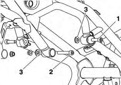
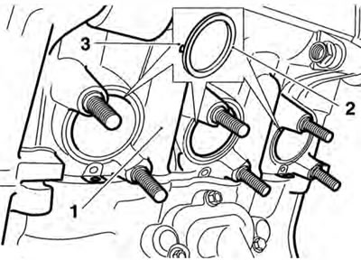
1. Left hand rear cylinder head bolt; 2. Left hand front cylinder head bolt; 3. Spacers
7. Fit the front cylinder head bolts from the outside. Fit new nuts but do not fully tighten at this stage.
Models Fitted with a Frame Adjuster Sleeve
1. Partially withdraw the rear lower engine mounting bolt (fitted at step 5) to allow tool T3880166 to be installed to the frame adjuster sleeve.
2. Using tool T3880166, tighten the rear frame adjuster sleeve to 3 Nm.
1. Frame adjuster sleeve; 2. Tool T3880166
Models Fitted with a Frame Adjustment Shim
Note: The shim must be selected and installed as described below.
1. Partially withdraw the rear lower engine mounting bolt (fitted at step 5) to allow a shim to be installed between the left hang frame boss and the crankcase.
2. Without using force, install the largest possible shim between the frame boss and the crankcase plate. Do not install more than one shim.
3. Shims are available in 0.5 mm increments from 0.5 mm to 3.5 mm.

1. Crankcase plate; 2. Frame boss; 3. Shim
All models
1. Fully insert the lower rear gearbox mounting bolt, refit the hardened washer and fit a new nut. Do not fully tighten at this stage.
Caution: Unless the following engine mounting bolt installation/ tightening sequence is precisely followed, severe frame damage can occur.
2. Tighten the engine mounting bolts as shown below.
- Tighten the right hand rear cylinder head (1) bolt to 48 Nm.
- Tighten the right hand front cylinder head (2) bolt to 48 Nm.
- Tighten the left hand rear cylinder head bolt (3) to 48 Nm.
- Tighten the left hand front cylinder head bolt (4) to 48 Nm.
- Tighten the rear lower rear gearbox mounting bolt (5) to 48 Nm.
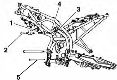
1. Right hand rear cylinder head bolt; 2. Right hand front cylinder head bolt; 3. Left hand rear cylinder head bolt; 4. Left hand front cylinder head bolt; 5. Rear lower rear gearbox mounting bolt
3. Refit the swinging arm (see page 12-15).
4. Refit the clutch cable (see page 4-5).
5. Reconnect all electrical connections to the engine.
6. Refit the gearchange linkage, aligning the slot in the gear selector arm with the dot on the gear change shaft. Refit the bolt and tighten to 9 Nm.
7. Refit the sprocket cover and tighten the bolts to 9 Nm.
8. Fit new exhaust seals to the cylinder head. Ensure that the face of the seal with the tab is facing the cylinder head.
1. Cylinder head; 2. Seal; 3. Seal tab
9. Refit the exhaust system (see page 10-95).
10. Refit the radiator (see page 11-12).
11. Fill the engine with oil of the correct grade and viscosity (see page 8-7).
12. Refit the throttle bodies (see page 10-107).
Warning: Operation of the motorcycle with incorrectly adjusted, incorrectly routed or damaged throttle cables could interfere with the operation of the brakes, clutch or the throttle itself. Any of these conditions could result in loss of motorcycle control and an accident.
Warning: Move the handlebars to left and right full lock while checking that cables and harnesses do not bind. Cables or harness that bind will restrict the steering and may cause loss of motorcycle control and an accident.
13. Check the throttle cable adjustment (see page 10-104).
14. Refit the airbox (see page 10-100).
15. Refit the fuel tank (see page 10-92).
16. Refit the battery to the battery box and reconnect, positive (red) lead first (see page 17-8).
17. Refill the cooling system (see page 11-5).
18. Remove the motorcycle from the paddock stand and place on the side stand.
19. Refit the seats (see page 16-13).