
Removal
Note: The input and output shafts may be removed from the upper crankcase after first separating the lower crankcase from the upper.
Note: The rear needle roller bearing on the input shaft remains in the crankcase on removal of the shaft.
1. Remove the engine from the frame (see page 9-3).
2. Separate the two halves of the crankcase (see page 5-4).
3. Lift the output shaft from the upper crankcase, noting the orientation of each bearing, their circlips and dowels.
4. Remove the selector fork shafts and forks (see page 7-7).
Note: The input shaft bearing housing fixings may not be re-used but should be retained for use during installation of the input shaft.
5. Release the three fixings and remove the retaining plate.
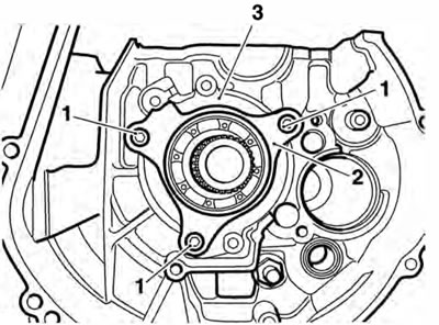
1. Fixings; 2. Retaining plate; 3. Bearing housing
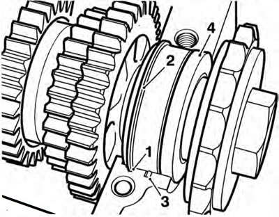
6. Insert two M6 bolts into the two threaded holes at the periphery of the bearing housing. Evenly and progressively tighten both bolts to draw the bearing housing and input shaft from the crankcase.
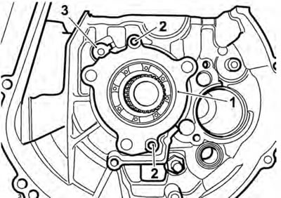
1. Bearing housing; 2. M6 threaded holes; 3. Transmission oil tube
7. If required, the transmission oil tube can now be removed. Remove and discard the three oil tube O-rings.
Installation
1. If removed, check the transmission oil tube for blockages and contamination. Carefully fit new O-rings to the transmission oil tube and insert the tube into the crankcase, ensuring the tag on the tube locates in the slot in the crankcase.
2. Locate the input shaft to the upper crankcase, installing it through the aperture for the bearing housing.
3. Fit the bearing housing into the aperture, by hand, as deeply as possible.
4. Using the old fixings, evenly and progressively tighten them to draw the bearing housing into the upper crankcase until fully home. Remove and discard the fixings.
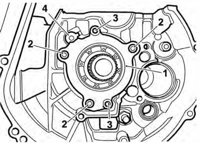
1. Bearing housing; 2. Fixings; 3. M6 threaded holes; 4. Transmission oil tube
5. Fit the retaining plate. Install new fixings and tighten to 12 Nm.
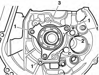
1. Fixings; 2. Retaining plate; 3. Bearing housing
6. Refit the selectors and shafts (see page 7-9).
7. Refit the output shaft to the crankcase ensuring the snap-ring locates in the corresponding groove in the crankcase, and the dowel locates in the slot in the upper crankcase.
8. Ensure the output shaft seal aligns with its recess in the crankcase.
1. Groove in crankcase; 2. Snap ring; 3. Dowel; 4. Seal
9. Ensure the hole in the output shaft needle roller bearing outer race is positioned to locate onto the dowel provided in the upper crankcase. Ensure the selector forks are located in the grooves in the output gears.
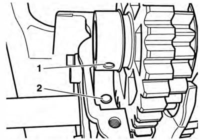
1. Roller bearing; 2. Dowel
10. Assemble the two halves of the crankcase (see page 5-4).
11. Refit the engine to the frame (see page 9-5).