
Caution! Cover or mask off the instrument cluster and trim to prevent scratches.
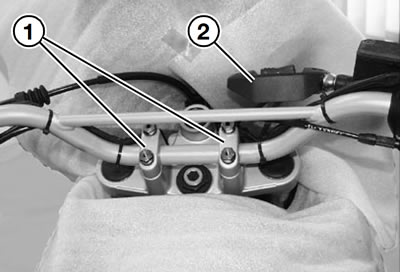
Remove impact pad (2).
Remove clamp blocks (1).
Remove the handlebar and place it in front of the instrument cluster.

Unscrew hex nut (5).
Release clamping screws (3) at upper fork bridge.
Unclip the clutch cable and the brake hose from their holders.
Cut through the 2 cable ties at the left of the frame head.
Cut through the 2 cable ties at the left of the frame head.
Remove the fasteners securing the oil tank and allow the oil tank to dangle to one side on the hoses.
Remove the starter relay from the holder.
Remove the lid of the electronic equipment box.
Cut through the cable tie holding the wiring harness at the electronic equipment box.
Disengage cover from the anchorage on main frame on left.

Disconnect plug for ignition lock (6).
Remove the cable complete with the plug.
Remove the upper fork bridge complete with the ignition lock.
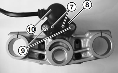
Remove securing screws (7) and remove ignition switch (10).
Using a 5 mm (0.20 in) bit, drill at least 6 mm (0.24 in) into the non-removable screws (9).
Using an 8 mm (0.31 in) bit, drill at least 5 mm (0.20 in) into the non-removable screws.
Break off the heads of the non-removable screws.
Remove the ignition lock (8) from the fork bridge.
Remove the shanks of the non-removable screws.
Installation is the reverse of the removal procedure: pay particular attention to the following.
Tighten the non-removable screws with socket wrench insert, BMW No. 51 0 530.
Warning! Begin by tightening the front securing screws (as viewed in the forward direction of travel) of the clamp blocks, then tighten the rear securing screws.
Tightening torques:
- Ignition/steering lock to fork bridge: 21 Nm
- Hexagon nut to counter-tube: 65 Nm
- Clamp screws for fork bridge: 23 Nm
- Handlebar to fork bridge: 23 Nm