
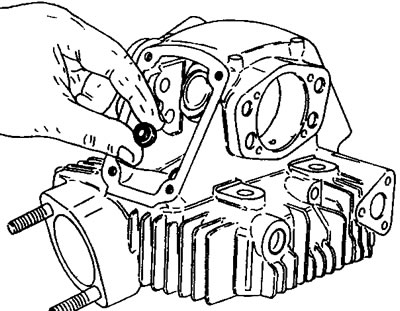
Insert the valves.

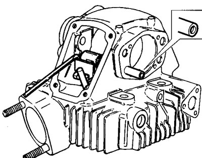
Place the lower rocker arm and spring on service tool 88713.0143.

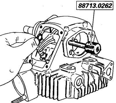
Insert the tool-rocker arm-spring assembly in the head and fit service tool 88713.0262 in place of the rocker arm pin.
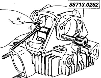
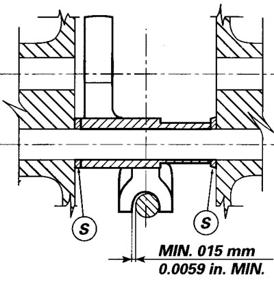
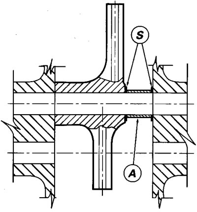
Adjust the side shim using the shims (S), positioning the rocker arm fork perfectly centered on the valve stem.
- minimum clearance between stem and rocker arm: 0.15 mm/0.0059 in.
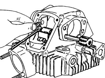
- The rocker arm must be free to move and must have an axial clearance of 0.05-0.20 mm/0.0019-0.0078 in.
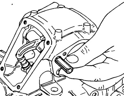
Remove the tool and position the rocker arm pin with the hole facing outwards.
Unhook the spring and remove the tool.
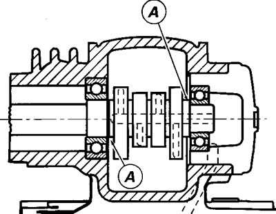
Position the cam shaft.

If you are changing the cam shaft, you must fit a shim (A) of 0.5 mm on both sides.
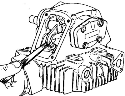
Rotate the cam shaft and use a screwdriver to lift the end part of the rocker arm with pad.
Position the return cap and the clamp split rings.

Fit the cam shaft cover so that the cam shaft is supported at both ends. With the valve in the rest position, (countering the force of the return spring by pushing on the rocker arm) check that the clearance between the rocker arm pad and the cams is correct. At the same time, ensure that the adjuster can be turned by hand.
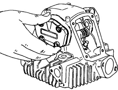
If not, measure the clearance between the lower rocker arm and the adjuster with a feeler gauge.
Remove the split rings and the adjuster.

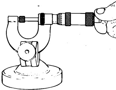
Check the thickness of the adjuster using a 0-25 mm micrometer, positioning the service pads as shown in the diagram.
Select the correct oversized adjuster (5 to 9.6 mm range), measured previously with a feeler gauge.
Refit the closing adjuster and the split rings.
Position the opening rocker arm adjuster.
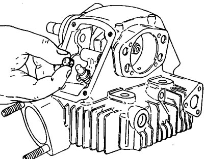
Position the opening rocker arm and the side spring (A) and adjust the side shim, using pin 88713.0262.
The shims (S) must be positioned at the sides of the spring (A); to obtain an axial clearance of 0.05+0.20 mm/0.0019-0.0078 in.
Remove the tool and position the rocker arm pin with the hole facing outwards.
Fit the cam shaft cover so that the cam shaft is supported at both ends With the valve in the rest position, check that the clearance between the rocker arm and the adjuster is correct.
Adjust the clearance by changing the upper adjuster with an adjuster with a different thickness (2 to 5 mm range).
Insert the side spring (A) in the opening rocker arm pin.
Caution! Before refitting the engine, check that the passage between the valves is at least 0.5 mm/0.0196 in.
Secure the cam shaft support cover with seal, tightening the screws at the specified torque values.
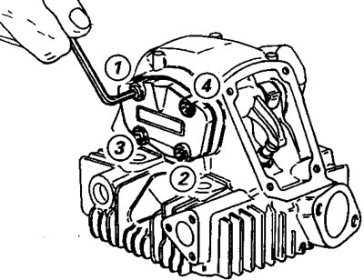
Follow the screw assembly sequence shown on the cam shaft cover.
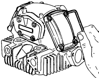
Secure the valve covers with seal and tighten the retaining screws.