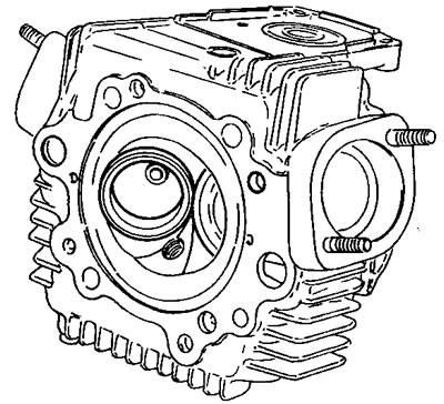
Valve seat
The valve seat must not be too recessed and must not show any signs of pitting or cracks.
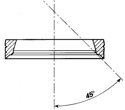
If the seat is slightly damaged, grind the valves and then mill the seat, using 45° single blade cutters.

Valve guide
Thoroughly check the inner surface of the valve guide: there must be no signs of cracks or deformation. If there is excessive oval, use a reamer to smooth the coupling surface.
Note. When you change the valve guide, you must also change the valve. The intake valve guides are cast-iron while the exhaust valve guides are bronze.
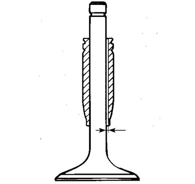
Valve
Check that the stem and the contact surface with the valve seat are in good condition. There must be no pitting, cracks, deformations or signs of wear.

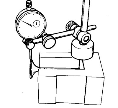
Perform the following tests: measure the diameter of the stem (B) at various heights of the valve working area in the valve guide. Check the concentricity of the head surface at 45° compared to the stem, by placing a dial gauge in a straight line with the head and turning the valve on a "V" reference block.
Wear limit: 0.03 mm/0.0012 in.
Valve-valve guide coupling
Coupling clearance: 0.02-0.05 mm/0.00078-0.00196 in.
Maximum wear limit: 0.08 mm/0.00314 in.
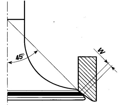
Valve-valve seat coupling
Check, using Prussian blue or a mixture of minium and oil, that the contact surface (W) between the valve and the seat is 1.0-1.5 mm/ 0.039-0.059 in.
Maximum limit: 2.0 mm/0.078 in.
If the dimension measured is higher than that indicated, grind the seat. Check, by filling the fuel intake and exhaust ducts, that there is no leakage; if there is, check that there are no burrs on the sealing surfaces.
Changing the valve guide
If you have to change the valve guide, proceed as follows:
- slowly and evenly heat the cylinder head in an oven to a temperature of 180°C/356°F;
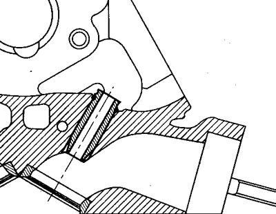
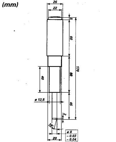
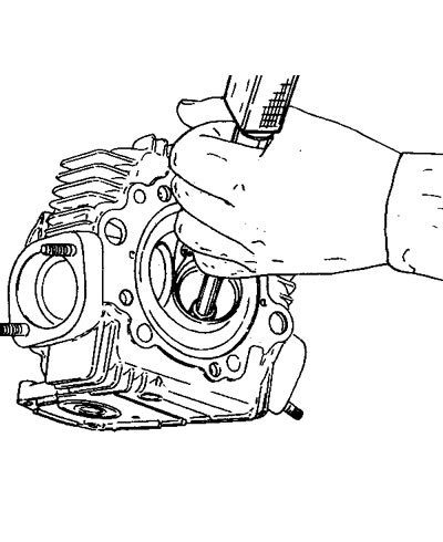
- Drive out the valve guide using a punch (see diagram);
- Let it cool and then check the conditions of the seat;
- Choose the most suitable valve guide, bearing in mind a fitting interference with the cylinder head of 0.022+0.051 mm/0.00086-0.00200 in;
- spare valve guides are supplied with an oversized outer diameter of 0.03, 0.06 and 0.09 mm, already fitted with the circlip;
- Heat the head again and cool the new valve guide with dry ice;
- Lubricate the seat and fit the valve guide. Drive the circlip to the end of the head, using the punch used for removing it;
- let the head cool and bore the inner hole:
- Exhaust valve guide inner diameter: 7.990-8.006 mm/0.3145-0.3152 in.
- Intake valve guide inner diameter: 7.980-8.000 mm/0.3141-0.3149 in.
 |  |
Changing the valve seat
Remove the worn seats and mill the rings. Ensure that you do not damage the location on the head.
Check the diameter of the locations on the head and choose the oversized valve seat bearing in mind that the fitting interference must be 0.11-0.16 mm/0.0043-0.0063 in. The spare valve seats are supplied with an oversized outer diameter of 0.03 and 0.06 mm.
slowly and evenly heat the cylinder head in an oven to a temperature of 180°C/356°F and cool the seats with dry ice.
Position the seats perfectly in square in their locations, using the punch described above.
Let it cool and then bore the seats, at the connection of the ducts with the new seats. Then grind the valves.
Caution! Do not use grinding paste after final milling.