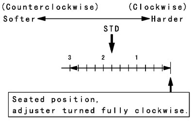
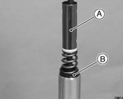
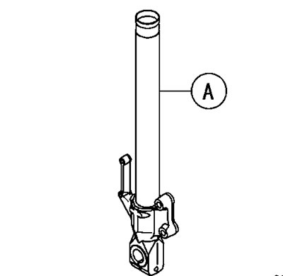
Rebound Damping Force Adjustment (Only Right Fork Leg)
- To adjust the rebound damping force, turn the rebound damping adjuster [A] on top of the right front fork leg to the desired position.
The standard adjuster setting for the average-build rider of 68 kg (150 lb) with no passenger and no accessories is 1 3/4 turns out from the fully clockwise position.
The damping force can be left soft for average riding. But it should be adjusted harder for high speed riding or riding with a passenger. If the damping feels too soft or too stiff, adjust it in accordance with the following table.
Rebound Damping Force Adjustment
| Adjuster Position | Damping Force | Setting | Load | Road | Speed |
| 3 | Weak | Soft | Light | Good | Low |
| ↑ | ↑ | ↑ | ↑ | ↑ | ↑ |
| ↓ | ↓ | ↓ | ↓ | ↓ | ↓ |
| 0 | Strong | Hard | Heavy | Bad | High |
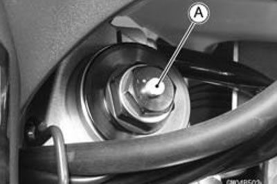
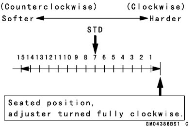
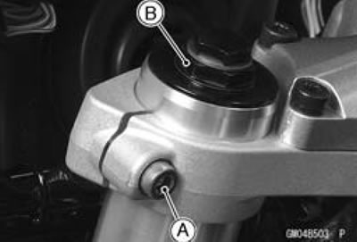
Spring Preload Adjustment
- Turn the spring preload adjuster [A] to change spring preload setting.
The standard adjuster setting for the average-build rider of 68 kg (150 lb) with no passenger and no accessories is 7 turns out from the fully clockwise position.

Warning: If both adjusters are not adjusted equally, handling may be impaired and a hazardous condition may result.
The spring preload can be left soft for average riding. But it should be adjusted harder for high speed riding or riding with a passenger. If the spring action feels too soft or too stiff, adjust it in accordance with the following table.
Spring Action
| Adjuster Position | Damping Force | Setting | Load | Road | Speed |
| 15 | Weak | Soft | Light | Good | Low |
| ↑ | ↑ | ↑ | ↑ | ↑ | ↑ |
| ↓ | ↓ | ↓ | ↓ | ↓ | ↓ |
| 0 | Strong | Hard | Heavy | Bad | High |
Front Fork Removal (Each Fork Leg)
Remove:
- Middle Fairings (See Middle Fairing Removal in the Frame chapter)
- Inner Cover (See Inner Cover Removal in the Frame chapter)
- Front Wheel (See Front Wheel Removal in the Wheels/Tires chapter)
- Front Fender (See Front Fender Removal in the Frame chapter)
- For models equipped with an ABS, remove the front wheel rotation sensor (see Front Wheel Rotation Sensor Removal in the Brakes chapter).
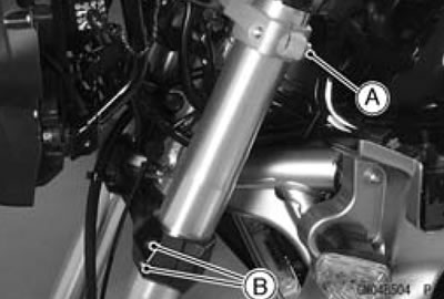
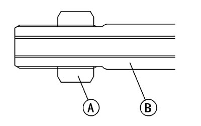
Loosen the upper fork clamp bolt [A] and top plug [B] beforehand if the fork leg is to be disassembled.
Note: Loosen the top plug after loosening the upper fork clamp bolts.
- Loosen the upper fork clamp bolt [A] and lower fork clamp bolts [B].
- With a twisting motion, work the fork leg down and out.
Front Fork Installation
- Install the fork so that the distance between the top end [A] of the outer tube and upper surface [B] of the steering stem head is the 12 mm (0.47 in.) [C].
- Tighten the lower fork clamp bolts and fork top plug.
Torque - Front Fork Clamp Bolts (Lower): 29 Nbm (3.0 kgf·m 21 ft·lb)
Front Fork Top Plug: 35 Nm (3.6 kgf·m, 26 ft·lb)
Note: Tighten the two lower fork clamp bolts alternately two times to ensure even tightening torque. Tighten the top plug before tightening the upper fork clamp bolts.
- Tighten the upper fork clamp bolt.
Torque - Front Fork Clamp Bolt (Upper): 20 Nm (2.0 kgf·m, 15 ft·lb)
- Install the removed parts (see appropriate chapters).
Adjust:
Spring Preload (See Spring Preload Adjustment) Rebound Damping Force (Right Fork Leg only, (See Rebound Damping Force Adjustment (Only Right Fork Leg))
Fork Oil Change
- Remove the front fork (See Front fork) Removal).
- Hold the inner tube lower end in a vice.
- Unscrew the top plug [A] out of the outer tube.
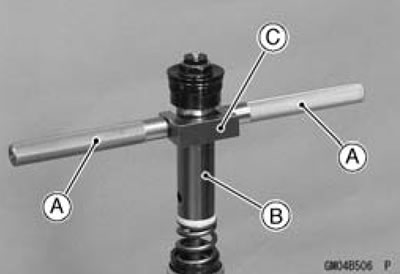
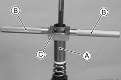
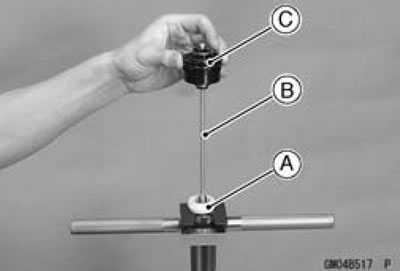
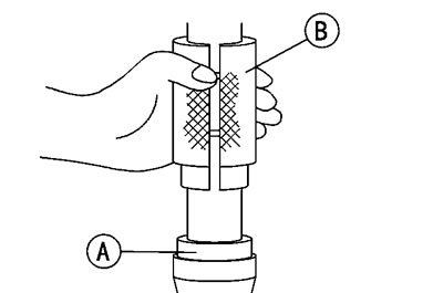
- Install the fork spring compressor as shown in the figure.
Note: Set the fork spring compressor so that the end of the handle [A] passes the upper side hole on the spacer [B] by screwing the handle in the holder [C] to the bottom.
Special Tool - Fork Spring Compressor: 57001-1685
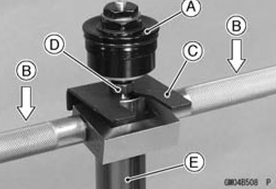
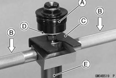
- While holding up the top plug [A] by one person, push down [B] the fork spring compressor and insert the fork spring stopper [C] between the piston rod nut [D] and the spacer [E].
Special Tool - Fork Spring Stopper: 57001-1374
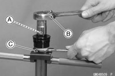
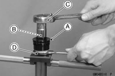
- Holding the spring preload adjuster [A] with a wrench [B], loosen the piston rod nut [C].
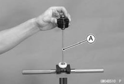
- Remove the top plug from the piston rod.
For the right fork leg, remove the top plug with the rebound damping adjuster rod [A].
Remove:
- Slider [A] Spacer [B] Damper [C]
- Fork Spring [D]
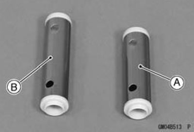
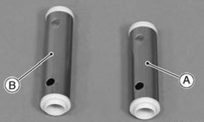
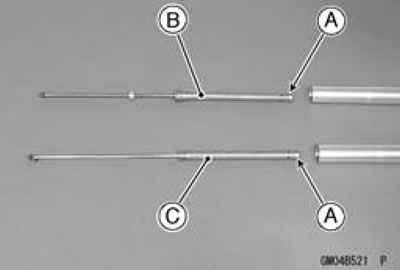
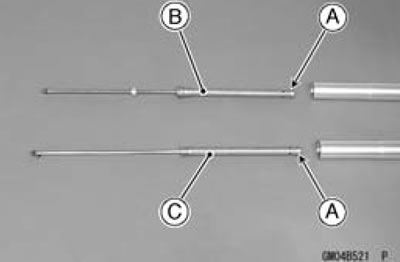
Note: The right fork leg spacer [A] is shorter than the left fork leg spacer [B].
- Drain the fork oil into a suitable container.
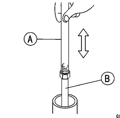
Pump the piston rod [A] up and down at least ten times to expel the oil from the fork.
Special Tool - Fork Piston Rod Puller, M10x1.0 [B]: 57001-1298
- Hold the fork tube upright, press the outer tube [A] and the piston rod all the way down.
- Pour in the type and amount of fork oil specified.
Fork Oil
SHOWA SS-8 or equivalent
Viscosity: SAE 10W
Amount (Right Fork Leg):
When changing oil: Approx. 410 mL (13.9 US oz.)
After disassembly and 478±2.5 mL (16.2±0.084 US completely dry: oz.)
Amount (Left Fork Leg):
When changing oil: Approx. 415 mL (14.0 US oz.)
After disassembly and 487±2.5 mL (16.5±0.084 US completely dry: oz.)
If necessary, measure the oil level as follows.
Hold the inner tube vertically in a vise.
Using the piston rod puller [A], move the piston rod [B] up and down more than ten times in order to expel all the air from the fork oil.
Special Tool - Fork Piston Rod Puller, M10 x 1.0: 57001-1298
Wait until the oil level settles.
With the fork fully compressed and the piston rod [B] fully pushed in, insert a tape measure or rod into the inner tube, and measure the distance from the top of the outer tube to the oil.
Oil Level (fully compressed, without spring)
Standard:
Right Fork Leg: 75±2 mm (3.0±0.08 in.) (from the top of the outer tube)
Left Fork Leg: 65±2 mm (2.6±0.08 in.) (from the top of the outer tube)
Note: Fork oil level may also be measured using the fork oil level gauge.
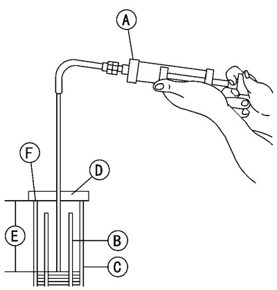
Special Tool - Fork Oil Level Gauge [A]: 57001-1290
With the fork fully compressed and without fork spring, insert the gauge tube into the inner tube [B] and position the stopper across the top end [F] of the outer tube [C].
Set the gauge stopper [D] so that its lower side shows the oil level distance specified [E].
Pull the handle slowly to pump out the excess oil until the oil no longer comes out.
If no oil is pumped out, there is insufficient oil in the inner tube. Pour in enough oil, then pump out the excess oil as shown above.
- Screw on the rod nut [A] fully to the piston rod [B].
- Screw the fork piston rod puller onto the end of the rod.
Special Tool - Fork Piston Rod Puller, M10 x 1.0: 57001-1298
- Install the fork spring [A] with the smaller end [B] facing upward.
Install:
- Spacer [A]
- Damper [B]
Note: The right fork leg spacer [A] is shorter than the left fork leg spacer [B].
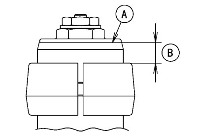
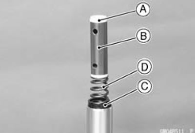
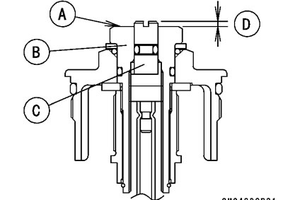
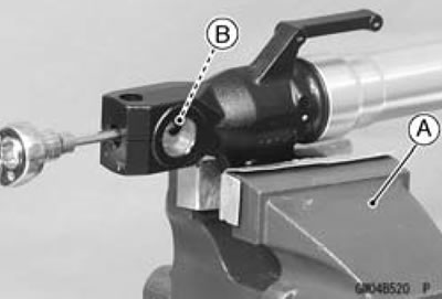
- For the right fork leg, check the distance between the upper end [A] of the spring preload adjuster [B] and rebound damping adjuster [C] with a pair of vernier caliper.
- 1.5 mm (0.059 in.) [D]
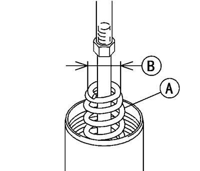
- Set the fork spring compressor on the spacer [A].
Special Tool - Fork Spring Compressor: 57001-1685
Note: Set the fork spring compressor so that the end of the handle [B] passes the upper side hole on the spacer by screwing the handle in the holder [C] to the bottom.
- While holding up the piston rod puller [A] by one person, push down [B] the fork spring compressor, and insert the fork spring stopper [C] between the piston rod nut [D] and the spacer [E].
Special Tool - Fork Spring Stopper: 57001-1685
- Remove the piston rod puller.
- Install the slider [A].
- For the right fork leg, insert the rebound damping adjuster rod [B] into the holes of the piston rod.
- Screw in the top plug [C] stopped onto the piston rod.
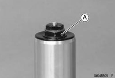
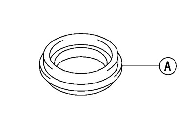
- Check the O-ring [A] on the top plug and replace it with a new one if damaged.
Apply grease to the new O-ring.
- Holding the spring preload adjuster [B] with a wrench [C], tighten the piston rod nut [D] against the top plug.
Torque - Piston Rod Nuts: 20 Nm (2.0 kgf·m, 15 ft·lb)
- While holding up the top plug [A] by one person, push down [B] the fork spring compressor, and pull out the fork spring stopper [C].
- Align the slider [D] with the spacer [E].
- Remove the fork spring compressor.
- Rise the outer tube and screw the top plug into it.
- Install the front fork (See Front Fork Installation).
Front Fork Disassembly
- Remove the front fork (See Front fork) Removal).
- Drain the fork oil (See Fork Oil Change).
- Hold the fork leg with a vise [A].
- Unscrew the Allen bolt [B], then take the bolt and gasket out of the bottom of the inner tube.
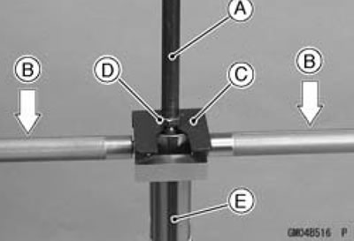
- Take the cylinder unit and center ring plate [A] out of the inner tube.
Do not disassemble the cylinder unit.
- Cylinder Unit [B] for Right Fork Leg
- Cylinder Unit [C] for Left Fork Leg
- Separate the inner tube from the outer tube as follows.
Slide up the dust seal [A].
Remove the retaining ring [B] from the outer tube.
Holding the inner tube [A] by hand, pull the outer tube [B] several times to pull out the outer tube.
- Remove the inner tube guide bushing [A], outer tube guide bushing [B], washer [C], oil seal [D] from the inner tube.
Front Fork Assembly
- Replace the following parts with new one.
- Oil Seal [A]
- Outer Tube Guide Bushing [B]
- Inner Tube Guide Bushing [C]
- Bottom Allen Bolt Gasket [D]
- Install the following parts onto the inner tube.
- Dust Seal [E]
- Retaining Ring [F]
- Oil Seal
- Washer [G]
- Outer Tube Guide Bushing
- Inner Tube Guide Bushing
- Insert the inner tube to the outer tube.
- Fit the new outer guide bush [A] into the outer tube.
Note: When assembling the new outer tube guide bushing [A], hold the washer against the new outer tube guide bushing and tap the washer with the fork oil seal driver [B] until it stops.
Special Tool - Fork Oil Seal Driver, ∅41: 57001-1288
- Install the oil seal by using the fork oil seal driver.
Special Tool - Fork Oil Seal Driver, ∅41: 57001-1288
- Install the retaining ring and dust seal into the outer tube.
- Install the center ring plate [A] on the cylinder unit.
- Insert the center ring plate and cylinder unit as a set into the inner tube.
- Cylinder Unit [B] for Right Fork Leg
- Cylinder Unit [C] for Left Fork Leg
- Hold the front fork in a vise.
Tighten:
Torque - Front Fork Bottom Allen Bolts: 20 Nm (2.0 kgf·m 15 ft·lb)
- Pour in the specified type of oil (See Fork Oil Change).
Inner Tube, Outer Tube Inspection
- Visually inspect the inner tube [A], and repair any damage.
- Nick or rust damage can sometimes be repaired by using a wet-stone to remove sharp edges or raised areas which cause seal damage.
If the damage is not repairable, replace the inner tube. Since damage to the inner tube damages the oil seal, replace the oil seal whenever the inner tube is repaired or replaced.
Caution: If the inner tube is badly bent or creased, replace it. Excessive bending, followed by subsequent straightening, can weaken the inner tube.
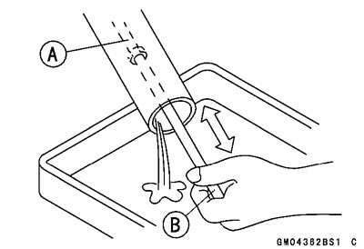
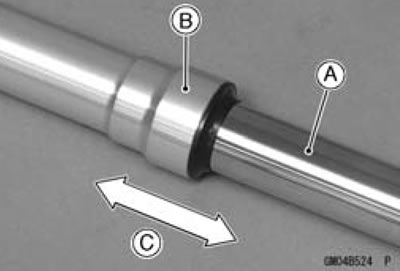
- Temporarily assemble the inner tube [A] and outer tube [B], and pump [C] them back and forth manually to check for smooth operation.
If you feel binding or catching, the inner and outer tubes must be replaced.
Warning: A straightened inner or outer fork tube may fall in use, possibly causing an accident. Replace a badly bent or damaged inner or outer tube and inspect the other tube carefully before reusing it.
Dust Seal Inspection
- Inspect the dust seals [A] for any signs of deterioration or damage.
Replace it if necessary.
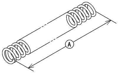
Spring Tension Inspection
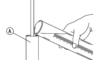
- Since a spring becomes shorter as it weakens, check its free length [A] to determine its condition.
If the spring of either fork leg is shorter than the service limit, it must be replaced. If the length of a replacement spring and that of the remaining spring vary greatly, the remaining spring should also be replaced in order to keep the fork legs balanced for motorcycle stability.
Spring Free Length
Standard: 292.9 mm (11.53 in.)
Service Limit: 287 mm (11.3 in.)