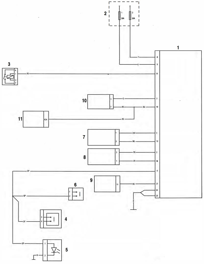
Key to Wiring Diagram
| Key | Item Description |
| 1 | ABS Modulator |
| 2 | Rear Fuse Box (Fuses 1 and 2) |
| 3 | Headlamp Relay |
| 4 | Front Brake Light Switch |
| 5 | Brake Light |
| 6 | Rear Brake Light Switch |
| 7 | Front Wheel Speed Sensor |
| 8 | Rear Wheel Speed Sensor |
| 9 | Instruments |
| 10 | Diagnostic Connector |
| 11 | Engine Control Module |
Key to wiring colour codes
| Code | Wiring Colour |
| B | Black |
| U | Blue |
| N | Brown |
| G | Green |
| S | Slate/Grey |
| О | Orange |
| K | Pink |
| R | Red |
| P | Purple |
| W | White |
| Y | Yellow |
| LG | Light Green |
| LU | Light Blue |
ABS ECM Connector Pin Numbering
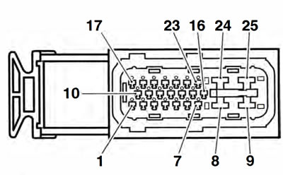
The above illustration shows the pin numbering system used in the ABS circuit diagram.
As viewed on the mating face with the ABS ECM (as per the illustration), pins are numbered from left to right with number one in the bottom left hand corner.
ABS System Circuit Diagram