Prepare
1. Remove engine. See Replace engine.
2. Remove starter. See Removing and installing starter.
3. Remove clutch. See Removing and installing clutch.
4. Remove cylinder head covers. See Cylinder head covers.
5. Remove cylinder heads. See Cylinder heads.
6. Remove cylinders. See Removing and installing cylinders.
7. Remove balancer shaft. See Removing and installing balancer.
8. Remove output pulley. See Output pulley.
Disassemble
Caution: Do not rotate crankcase half in engine stand when flywheel is installed. The flywheel assembly can fall out, resulting in parts damage or moderate injury.
1. Rotate crankcase clutch side down.
2. See Figure 4-47. Separate crankcase halves.
- a. Discard crankcase screws.
- b. Separate crankcase halves.
Assemble
| FASTENER | TORQUE VALUE | |
| Crankcase M8 screws | 20.0-25.0 Nm | 15-18 lb·ft |
| Crankcase M6 screws | 10.0-12.0 Nm | 89-106 in·lbs |
1. Secure right crankcase half in engine stand, a. Place clutch side down.
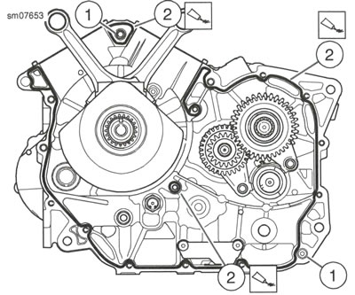
2. See Figure 4-46. Apply a (3-5 mm) (0.12-0.20 in) wide bead of HIGH-PERFORMANCE SEALANT, GRAY Part NO. 99650-02 (2) only in the areas shown.
3. Install left crankcase.
- a. Align crankcase on dowel pins (1).
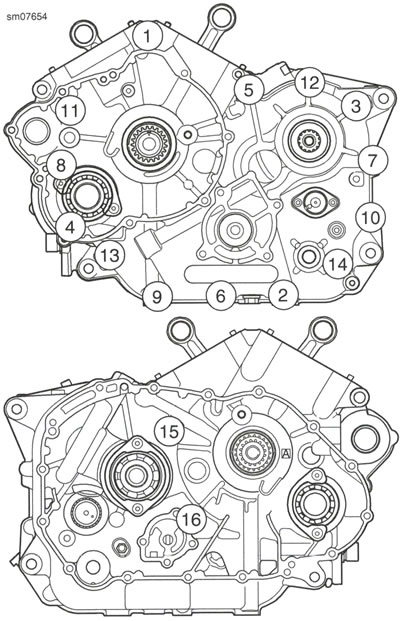
4. See Figure 4-47. Install new crankcase fasteners. Tighten finger-tight.
- a. Long screws (1,5).
- b. Medium screws (8, 11).
- c. Short screws (2-4, 6, 7, 9, 10, 12-16).
5. Tighten screws in sequence shown.
- a. M8 screws: 20.0-25.0 Nm (15-18 lb·ft).
- b. M6 screws: 10.0-12.0 Nm (89-106 in·lbs).

Figure 4-46. Right Crankcase: 1. Dowel pin (2) 2. Sealant

Figure 4-47. Crankcase Tightening Sequence:
Complete
1. Install output pulley. See Output pulley.
2. Install balancer shaft. See Removing and installing balancer.
3. Install cylinders. See Removing and installing cylinders.
4. Install cylinder heads. See Cylinder heads.
5. Install cylinder head covers. See Cylinder head covers.
6. Install clutch. See Removing and installing clutch.
7. Install starter. See Removing and installing starter.
8. Install engine. See Replace engine.
