
Prepare
1. Remove exhaust system. See Exhaust system.
2. Remove clutch. See Removing and installing clutch.
Remove Oil Pump
Note: Oil pressure relief valve is located in oil pump. Oil pressure relief valve is not serviceable. Replace oil pump as necessary.
1. See Figure 4-44. Remove gear.
- a. Discard retaining ring (1).
- b. Remove gear (2).
- c. Remove gear pin (3).
2. Remove housing.
- a. Remove screws (6).
- b. Remove housing (7).
3. Remove oil pump assembly.
- a. Remove shaft (4), inner gerotor (8) and inner gerotor Pin (5).
- b. Remove outer gerotor (9).
Oil Filter Adapter
1. See Figure 4-44. Remove oil filter adapter (10).
Install
| FASTENER | TORQUE VALUE | |
| Oil pump housing screws | 10.0-12.0 Nm | 89-106 in·lbs |
| Oil filter adapter | 20.0-25.0 Nm | 15-18 ft·lbs |
Oil Pump
Note: The T marking on both the inner and outer gerotor must face the crankcase.
1. See Figure 4-44. Install oil pump.
- a. Install outer gerotor (9).
- b. Install inner gerotor pin (5) in shaft (4).
- c. Install inner gerotor (8) over inner gerotor pin (5).
- d. Install shaft and inner gerotor assembly in outer gerotor (9).
2. Install housing.
- a. Install housing (7).
- b. Install screws (6). Tighten to 10.0-12.0 Nm (89-106 in·lbs).
3. Install gear.
- a. Install pin (3).
- b. Install gear (2).
- c. Install new retaining ring (1).
Oil Filter Adapter
1. See Figure 4-44. Install oil filter adapter (10). Tighten to 20.0-25.0 Nm (15-18 ft·lbs).
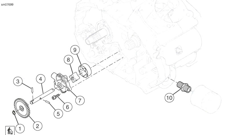
Figure 4-44. Oil Pump Assembly: 1. Retaining ring; 2. Gear; 3. Gear pin; 4. Shaft; 5. Inner gerotor Pin; 6. Screw (4); 7. Housing; 8. Inner gerotor; 9. Outer gerotor; 10. Oil filter adapter
Complete
1. Install clutch. See Removing and installing clutch.
2. Install exhaust system. See Exhaust system.