
| PART NO. | SPECIALTY TOOL |
| HD-45317 | Engine assembly support fixture |
1. See Figure 2-8. On a table lift with a lift side extension, position a scissors jack under the fuel tank.
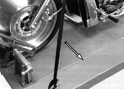
Figure 2-8. Lift side extension
Note. To provide clearance and alignment, locate a scissors style jack under the fuel tank frame extensions to raise or lower the motorcycle throughout the procedure.
Warning! The gasoline in the fuel supply line downstream of the fuel pump is under high pressure (400 kPa, 58 psi). To avoid an uncontrolled discharge or spray of gasoline, always purge the system of high pressure gas before removing the fuel supply line from the fuel tank. Gasoline is extremely flammable and highly explosive. Inadequate safety precautions could result in death or serious injury.
2. Open seat and remove or lift fuel filler boot.
3. Purge fuel supply line of high pressure gasoline.
a. Disconnect fuel module connector from top plate.
b. In neutral, start engine and allow engine to run.
c. When engine stalls, operate starter for 3 seconds to remove any remaining fuel from fuel lines.
4. Place a suitable container under engine, loosen oil drain plug and drain oil.
5. Replace and torque oil drain plug to 35 Nm (25 ft-lbs).
6. Allow engine to cool.
- a. For replacement engines, leave oil filter threaded into its mounting plate.
- b. For engine overhaul, remove oil filter as necessary.
Important note. Dispose of oil in accordance with local regulations.
7. Remove right side cover and maxi-fuse. See 8.5 Maxi-fuse.
8. Remove air filter cover. See 1.4 Airbox and air filter.
Warning! To protect against shock and accidental start-up of vehicle, disconnect the negative battery cable before proceeding. Inadequate safety precautions could result in death or serious injury.
9. See Figure 2-9. Disconnect negative (1) and positive (2) battery cables from battery.
10. Remove air filter top, air filter, breather hose, velocity stacks, and air filter bottom. Unscrew threaded air filter hold down rod from throttle body. See 1.4 Airbox and air filter.
11. At the fuel rail, disconnect pressure fuel line and return fuel line by pressing blue buttons with thumb and first finger.
12. See Figure 2-9. Disconnect copper L-bracket (4) with negative battery cable (3) from front cylinder head.
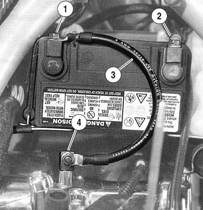
Figure 2-9. Battery cable connections: 1. Negative battery cable at battery; 2. Positive battery cable at battery; 3. Negative battery cable; 4. L-bracket with negative battery cable
13. See Figure 2-11. Remove fastener on rear cylinder head and remove GND 1 (8), GND 2 (9), and ground wire (10) to horn. Replace fastener.
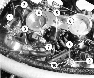
Figure 2-11. Wiring connections: 1. Negative battery cable copper L-bracket; 2. Front cylinder coil connector; 3. Regulator ground; 4. Throttle position sensor connector; 5. Idle air control actuator connector; 6. Purge solenoid fitting; 7. Main engine sensor connector; 8. GND1; 9. GND 2; 10. Horn ground wire
14. Remove fastener on front cylinder head and remove regulator ground (3). Replace fastener.
15. Disconnect wiring connectors from horn. Unbolt and remove horn from rubber grommet on frame.
16. Disconnect:
- a. Front (2) and rear coil connectors.
- b. Main engine sensor connector (7).
- c. Throttle position sensor (4).
- d. Idle air control actuator (5).
17. For a California model, pull the purge solenoid hose (6) off throttle body.
18. Perform throttle body procedure:
a. For a replacement engine, loosen throttle cable adjustor jam nuts. Turn throttle cable adjuster until cable is as short as possible. Remove throttle cable housings from guides at the throttle body and remove cable barrels from throttle cam. See 2.12 Throttle cables.
b. See Figure 2-10. For engine overhaul, loosen clamps at each intake and lift throttle body straight up. With throttle cables attached, wrap a shop towel around body for protection and secure away from engine. Cover intake openings to prevent objects from falling into intake bore.
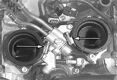
Figure 2-10. Intake clamps (throttle body removed)
Note. For replacement engines, the engine wiring harness is left attached to the engine. The engine wiring harness will include connectors to the manifold air pressure sensor, the intake air temperature sensor, the coolant temperature sensor, the oil pressure sending unit, and both fuel injectors.
19. Remove lower left and right side radiator covers. See 6.8 Radiator/oil cooler.
20. See Figure 2-12. Disconnect:
- a. Crank position sensor connector (3).
- b. Top and bottom fan power connectors (2).
- c. Stator to voltage regulator connector (1).
- d. Wiring frame clip (4).
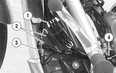
Figure 2-12. Left side wiring connectors: 1. Stator to regulator connector; 2. Top and bottom fan power connectors; 3. Crank position sensor connector; 4. Wiring frame clip
Note. Observe the position of the clamps for reassembly.
21. See Figure 2-13. Cover front fender with a shop towel or protective cover. On right side, pull rear brake fluid reservoir from radiator cover. Remove two fasteners and washers (2) on each side of radiator cover and remove radiator cover. The radiator cover includes two chrome inlet bezels.

Figure 2-13. Radiator cover left side: 1. Drain plug; 2. Cover fastener and washer
Warning! Allow engine to cool before opening the radiator cap to work on the liquid cooling system. Coolant can be extremely hot and at high pressure. Opening a hot cooling system may result in death or serious injury.
22. Place a suitable container under radiator and open pressure cap.
23. See Figure 2-13. Remove drain plug (1) and drain coolant from radiator. Leave container under engine until all coolant has been drained through front cylinder coolant drain plug.
24. Replace radiator drain plug (1) and tighten to 9-11 Nm (80-97 in-lbs).
25. Use a long thin screwdriver (Snap-on Part No. SDD1410) to loosen worm drive clamps on radiator hoses.
26. Loosen and remove cross member fasteners from lower left frame rail.
27. Put radiator/oil cooler assembly forward at the bottom. Loosen and unthread oil line sleeves (18) at crankcase (oil in) and oil filter (oil out) mount.
28. Remove radiator/oil cooler assembly. See 6.8 Radiator/oil cooler.
29. See Figure 2-14. Finish draining coolant by removing front cylinder coolant drain plug. Replace front cylinder coolant drain plug and tighten to 9.7 Nm (86 in-lbs).
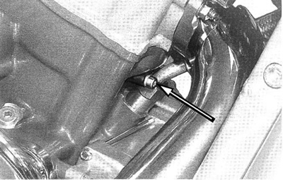
Figure 2-14. Front cylinder coolant drain plug
30. Remove engine coolant pipes. See 6.6 Coolant pipesand hoses.
Important note. Dispose of antifreeze in accordance with local regulations.
31. Remove drive sprocket cover. Remove debris deflector/ belt guard if required for clearance.
32. See Figure 2-15. Loosen and remove bolts (3) holding drive sprocket locking device. Discard bolts.
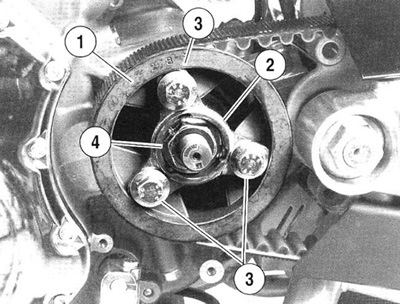
Figure 2-15. Drive sprocket: 1. Drive sprocket; 2. Sprocket flange locking device; 3. Retaining bolt; 4. Sprocket nut
Note. Do not remove the sprocket nut.
33. Loosen rear wheel axle nut. Move wheel forward and slip belt off drive sprocket.
34. See Figure 2-15. Remove retaining bolts (3). Remove drive sprocket (1).
35. Remove exhaust system. See 2.7 Exhaust system.
36. Remove secondary clutch actuator cover and secondary clutch actuator. See 2.16 Secondary clutch actuator.
Note. It is not necessary to loosen flare nut or to remove clutch fluid line from the secondary clutch actuator. Allow secondary clutch actuator to hang from clutch fluid line.
37. At front of engine, pull back solenoid cable protective boot from starter post and loosen and remove nut. Remove solenoid cable terminal ring. See 5.4 Starter.
38. Remove nuts holding starter solenoid to frame and pull solenoid off of frame studs. See 5.5 Starter solenoid.
39. See Figure 2-16. Position ENGINE ASSEMBLY SUPPORT FIXTURE (Part No. HD-45317) under engine. Align the two hex socket-head bolts (2) at rear of fixture with mounting screw detents (4) at bottom rear of oil pan. Align the two separated hex head bolts (1) on each side of front of fixture with corresponding mounting screw detents (3) on sides of oil pan. Using scissors jack, lower motorcycle until engine oil pan screw detents rest on hex socket-head bolts.
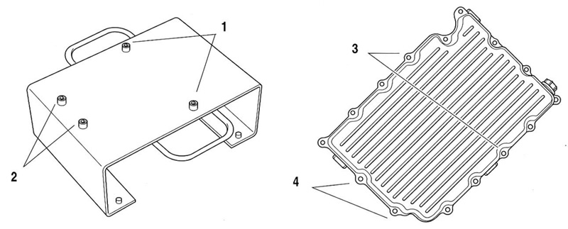
Figure 2-16. Engine assembly support fixture alignment: 1. Hex socket-head bolt - side; 2. Hex socket-head bolt - rear; 3. Mounting screw detents - side; 4. Mounting screw detents - rear
40. Remove nut and travel limiting washer from center motor mount bolt. Remove center mounting bolt.
41. Remove fasteners holding front motor mount bracket to engine.
42. Remove studs securing frame motor mount bracket to frame. Pull front motor mount assembly forward through frame rails.
43. Remove tie link bolt and spacer from engine case. See 2.5 Front engine mount.
Note. Maintain tie link length for reinstallation. Do not loosen jam nuts on tie link.
44. Remove rear fork pivot nut and slide out pivot shaft. Rear fork can be left in place.
45. Loosen fasteners holding rear engine mount bracket. See 2.8 Rear engine mounts.
46. Remove shifter arm with linkage attached from engine shifter shaft.
47. Remove engine ground cable from frame.
48. Remove lower left frame rail with footrest, foot shift lever/ linkage, and tie link attached. See 2.4 Frame/lower frame rails.
Caution! Do not push on the engine to move the engine. Support the engine and pull on the fixture handles.
49. With engine resting in ENGINE ASSEMBLY SUPPORT FIXTURE (HD-43517), gently pull on handles to work engine partially out of left side of frame.
50. See Figure 2-17. Pull connectors to neutral light sender under drive sprocket.
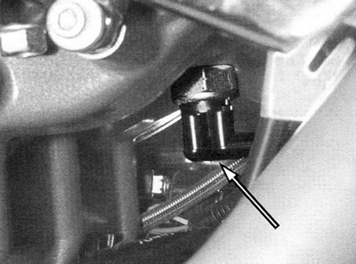
Figure 2-17. Neutral light sender connectors
Note. The neutral light sender stays in the engine.
51. Pull purge solenoid hose off of charcoal canister (California models only).
52. See Figure 2-18. Pull connectors from stoplamp switch.
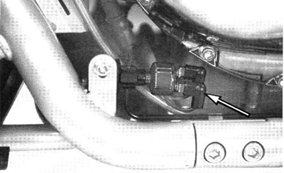
Figure 2-18. Stoplamp switch connectors
53. Pull electrical harness to stoplamp switch and purge solenoid hose (California models only) through top of the cavity in engine cases.
54. See Figure 2-19. Disconnect vehicle speed sensor wire from connector at top of frame under relay block and pull wire and connector down out of frame.
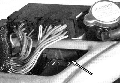
Figure 2-19. Vehicle speed sensor connector
Note. The vehicle speed sensor and wire connector stay attached to the engine.
55. With fixture handles, pull engine out of frame onto left side extension.
56. See Figure 2-20. Engine may be secured with straps for hoisting.
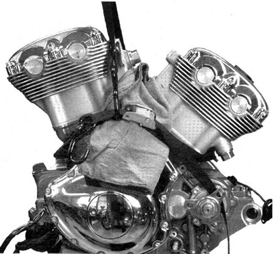
Figure 2-20. Engine strapped for hoisting