
Disassembly
Note: lt is not necessary to remove the connecting rods from the crankshaft.
1. Remove the cylinder head (see page 3-20)
2. Remove the liner, using the frame from tool T3880315, and tool T3880101 (see page 5-17).
3. Remove and discard the gudgeon pin circlip from one side of the piston.
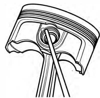
Removing the Gudgeon Pin Circlip
4. Remove the gudgeon pin by pushing the pin through the piston and rod toward the side from which the circlip was removed.
Caution: Never force the gudgeon pin through the piston. This may cause damage to the piston which may also damage the liner when assembled.
Note: If the gudgeon pin is found to be tight in the piston, check the piston for a witness mark caused by the circlip. Carefully remove the mark to allow the pin to be removed.
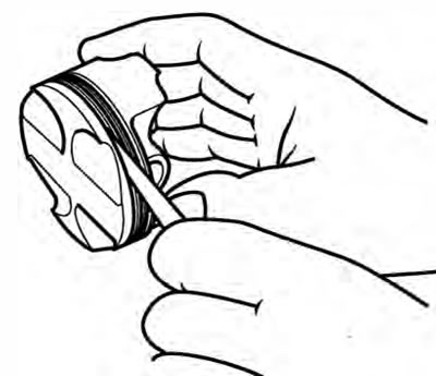
5. Piston rings must be removed from the piston using hand pressure only. Do not over-extend the piston rings during removal.
Note: If the piston rings are to be re-used, note the orientation of the oil control rings prior to removal.
Piston Wear Check
1. Measure the piston outside diameter, 8 mm up from the bottom of the piston and at 90° to the direction of the gudgeon pin.
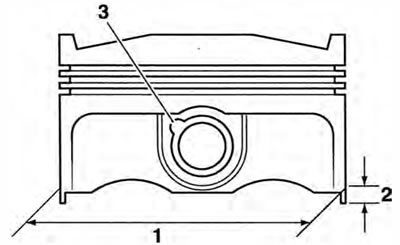
1. Piston outside diameter; 2. Measurement point; 3. Circlip removal groove
- All Cylinders: 73.974 - 73.990 mm
- Service limit: 73.930 mm
Replace the piston if the measured diameter falls outside the specified limit.
Piston Rings/Ring Grooves
Check the pistons for uneven groove wear by visually inspecting the ring grooves.
If all the rings do not fit parallel to the groove upper and lower surfaces, the piston must be replaced.
Clean the piston ring grooves.
Fit the piston rings to the pistons. Check, using feeler gauges, for the correct clearance between the ring grooves and the rings. Replace the piston and rings if outside the specified limit.
Piston Ring to Ring Groove Clearance Check
Piston ring/Groove Clearance
| Top ring Service limit | 0.020 - 0.060 mm 0.075 mm |
| Second Service limit | 0.020 - 0.060 mm 0.075 mm |
Piston Ring Gap
Note: The piston ring gap, with the piston ring fitted in the liner, must be checked before final assembly.
1. Place the piston ring inside the liner.
2. Push the ring into the top of the cylinder, using the piston to hold the ring square with the inside of the bore. Continue to push the ring into the bore until the third groove of the piston is level with the cylinder top, around the full circumference of cylinder.
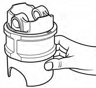
Aligning Piston Rings using the Piston
1. Remove the piston and measure the gap between the ends of the piston ring using feeler gauges.
Piston Ring End Gap Tolerances
| Top Service limit | 0.15 - 0.30 mm 0.60 mm |
| Second Service limit | 0.30 - 0.45 mm 0.75 mm |
| Oil Control Service limit | 0.20 - 0.70 mm 1.00 mm |
Note:
- If the end gap is too large, replace the piston rings with a new set
- If the gap remains too large with the new piston rings, both the pistons and barrels must be replaced
- If the gap is too small, check the cylinder bore for distortion, replacing as necessary. Do not file piston rings!
Piston Assembly
1. Clean the piston ring grooves and fit the piston rings to the piston.
Note:
- The top ring upper surface is marked 'N' and can be identified by a chamfer on the inside edge.
- The second ring upper surface is marked 'N2', and is plain on the inside edge
- When new, the oil control rings can be fitted with either face upward. Used oil control rings must be refitted in the same orientation as noted prior to removal.
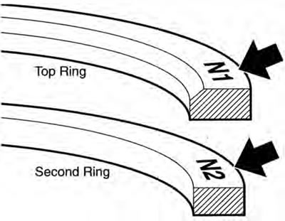
Piston Ring Identification
1. Fit the piston onto the connecting rod.
Note: Connecting rods may be fitted either way around. However, ensure all three are fitted the same way.
2. Lubricate the piston, small end and gudgeon pin with a 50150 solution of engine oil and molybdenum disulphide grease.
3. Align the small end in the connecting rod with the gudgeon pin hole in the piston and fit the gudgeon pin.
4. Fit new circlips on both sides of the gudgeon pin ensuring the circlips are correctly fitted in the grooves.
Warning: Failure to use new gudgeon pin circlips could allow the pin to detach from the piston. This could seize the engine and lead to an accident.
5. The piston ring gaps must be arranged as shown in the diagram below.
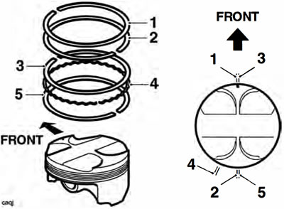
1. Top ring; 2. Second ring; 3. First steel oil control ring; 4. Oil control ring expander; 5. Second steel oil control ring
Note: The top ring gap should be positioned in the 12 o'clock position, and the second ring gap in the 6 o'clock position. The first steel oil control ring gap should be in the 12 o'clock position and the second steel oil control ring should be in the 6 o'clock position. The oil control ring expander should be in the 7 o'clock position.
6. Fit the piston into the liner from below using a gentle rocking motion to engage the rings in the bore.
Cylinder Wear
Measure the inside diameter of each cylinder using an internal micrometer or similar accurate measuring equipment.
Cylinder bore diameter
- Standard: 74.040 - 74.060 mm
- Service limit: 74.150 mm
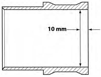
Test Position For Bore Wear Check (bore shown in section)
1. Measure the inside diameter 10 mm from the top of the bore as shown above.
2. If the reading is outside the specified limits, replace the liner and piston as an assembly.