Main Throttle Sensor Removal/Adjustment
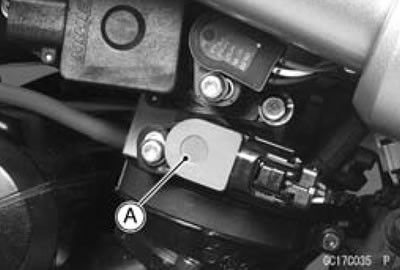
Caution: Do not remove or adjust the main throttle sensor [A] since it has been adjusted and set with precision at the factory. Never drop the throttle body assy, especially on a hard surface. Such a shock to the sensor can damage it.
Main Throttle Sensor Input Voltage Inspection
Note: Be sure the battery is fully charged.
- Turn the ignition switch OFF.
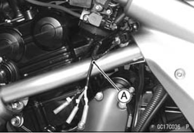
- Disconnect the main throttle sensor connector and connect the harness adapter [A] between these connectors.
Special Tool - Throttle Sensor Setting Adapter: 57001 -1538
- Connect a digital meter to the harness adapter lead.
Main Throttle Sensor Input Voltage
Connections to Adapter
- Meter (+) → BK (sensor BL) lead
- Meter (-) → W (sensor BR/BK) lead
- Measure the input voltage with the engine stopped and with the connector joined.
- Turn the ignition switch ON.
Input Voltage at Sensor
Standard: DC 4.75-5.25 V
- Turn the ignition switch OFF.
If the input voltage is normal, check the output voltage.
- If the input voltage is less than the standard, remove the ECU and check the wiring between these connectors.
Disconnect the ECU and sensor connectors.
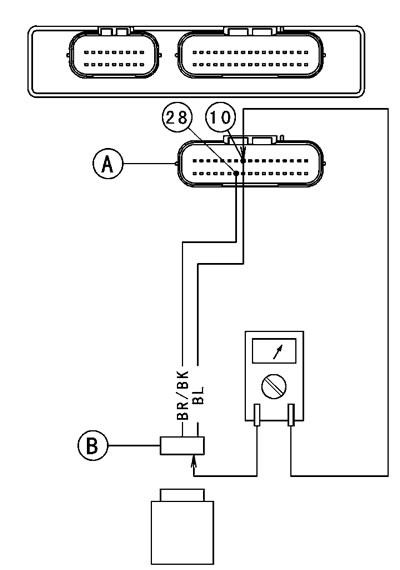
Wiring Connection
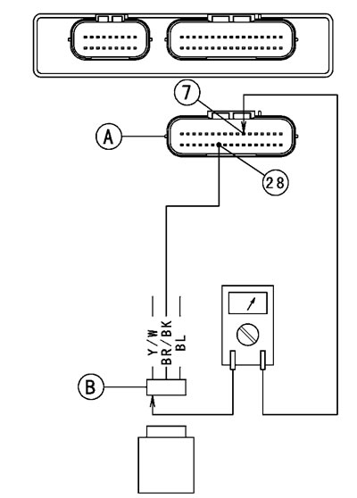
- ECU Connector [A] <—>
- Main Throttle Sensor Connector [B]
- BL lead (ECU terminal 10)
- BR/BK lead (ECU terminal 28)
If the wiring is good, check the ECU for its ground and power supply (See ECU Power Supply Inspection).
If the ground and power supply are good, replace the ECU (See ECU Removal/Installation).
Main Throttle Sensor Output Voltage Inspection
- Measure the output voltage at the main throttle sensor in the same way as input voltage inspection, Note the following.
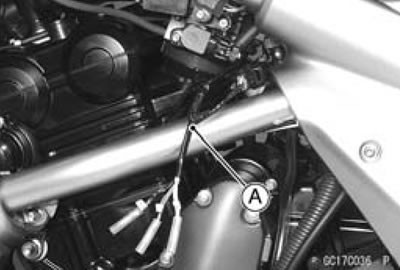
Disconnect the main throttle sensor connector and connect the harness adapter [A] between these connectors.
Special Tool - Throttle Sensor Setting Adapter: 57001 -1538
Main Throttle Sensor Output Voltage
Connections to Adapter
- Meter (+) → R (sensor Y/W) lead
- Meter (-) → W (sensor BR/BK) lead
- Start the engine and warm it up thoroughly.
- Check idle speed to ensure the throttle opening is correct.
Idle Speed
Standard: 1 300±50 r/min (rpm)
If the idle speed is out of the specified range, adjust it (See Idle Speed Inspection in the Periodic Maintenance chapter).
- Turn the ignition switch OFF.
- Measure the output voltage with the engine stopped, and with the connector joined.
- Turn the ignition switch ON.
Output Voltage at Sensor
Standard: DC 1.005-1.035 V (at idle throttle opening)
DC 4.2-4.4 V (at full throttle opening)
- Turn the ignition switch OFF.
If the output voltage is out of the standard, inspect the main throttle sensor resistance (See Main Throttle Sensor Resistance Inspection).
If the output voltage is normal, check the wiring for continuity.
Disconnect the ECU and sensor connectors.
Wiring Connection
- ECU Connector [A] <—>
- Main Throttle Sensor Connector [B]
- Y/W lead (ECU terminal 7)
- BR/BK lead (ECU terminal 28)
If the wiring is good, check the ECU for its ground and power supply (See ECU Power Supply Inspection).
If the ground and power supply are good, replace the ECU (See ECU Removal/Installation).
Main Throttle Sensor Resistance Inspection
- Turn the ignition switch OFF.
- Disconnect the main throttle sensor connector.
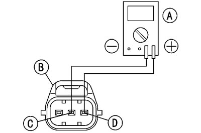
- Connect a digital meter [A] to the main throttle sensor connector [B].
- Measure the main throttle sensor resistance.
Main Throttle Sensor Resistance
Connections: BL lead [C] <—> BR/BK lead [D]
Standard: 4-6 kΩ
If the reading is out of the range, replace the throttle body assy.
If the reading is within the range, but the problem still exists, replace the ECU (See ECU Removal/Installation).
Main Throttle Sensor Circuit
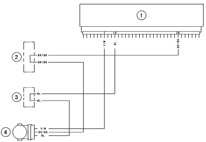
1. ECU; 2. Water-proof Joint E; 3. Water-proof Joint D; 4. Main Throttle Sensor
