Caution: Never drop the sensor, especially on a hard surface. Such a shock to the part can damage it.
Inlet Air Pressure Sensor Removal
- Remove the left middle fairing (See Middle Fairing Removal in the Frame chapter).
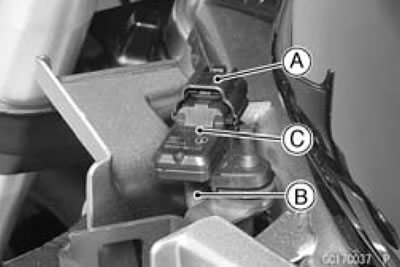
- Disconnect the inlet air pressure sensor connector [A] and the vacuum hose [B].
- Pull out the inlet air pressure sensor [C] from the bracke
Inlet Air Pressure Sensor Installation
Installation is the reverse of removal.
Inlet Air Pressure Sensor Input Voltage Inspection
Note: Be sure the battery is fully charged. The inspection is the same as "Input Voltage Inspection" of the main throttle sensor.
- Turn the ignition switch OFF.
- Remove the ECU (See ECU Removal).
Do not disconnect the ECU connectors.
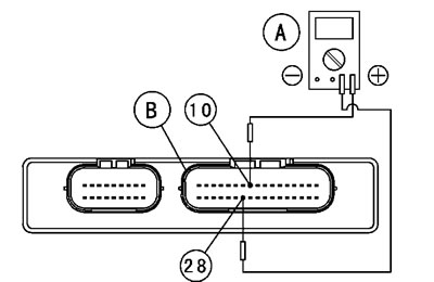
- Connect a digital meter [A] to the connector [B] with the needle adapter set.
Special Tool - Needle Adapter Set: 57001-1457
Inlet Air Pressure Sensor Input Voltage Connections to ECU Connector
Meter (+) → BL lead (terminal 10)
Meter (-) → BR/BK lead (terminal 28)
- Measure the input voltage with the engine stopped, and with the connectors joined.
- Turn the ignition switch ON.
Input Voltage at ECU
Standard: DC 4.75-5.25 V
If the reading is within the standard range, check the output voltage.
If the reading is less than the standard range, remove the ECU and check the wiring between these connectors.
If the wiring is good, check the ECU for its ground and power supply (See ECU Power Supply Inspection).
If the ground and power supply are good, replace the ECU (See ECU Removal/Installation).
Air Pressure Sensor Output Voltage Inspection
Note: The output voltage changes according to the local atmospheric pressure.
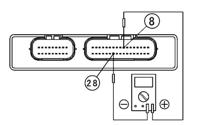
- Measure the output voltage at the ECU in the same way as input voltage inspection. Note the following.
Special Tool - Needle Adapter Set: 57001-1457
Inlet Air Pressure Sensor Output Voltage
Connections to ECU Connector
- Meter (+) → Y/BL lead (terminal 8)
- Meter (-) → BR/BK lead (terminal 28)
Usable Range: DC 3.80-4.20 V at the standard atmospheric pressure (101.32 kPa, 76 cmHg abs.)
- Turn the ignition switch OFF.
If the output voltage is within the usable range, check the ECU for its ground, and power supply (See ECU Power Supply Inspection).
If the ground and power supply are good, replace the ECU (See ECU Removal/Installation).
If the output voltage is out of the usable range, check the wiring.
If the wiring is good, check the sensor for various vacuum.
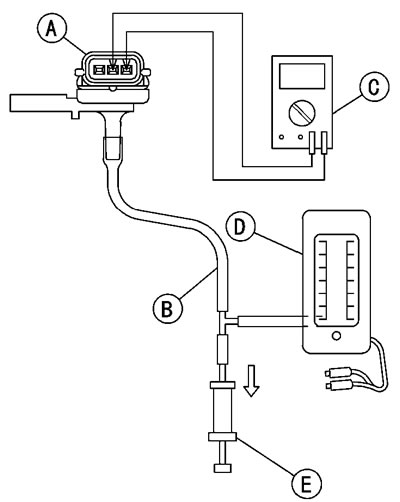
- Remove the inlet air pressure sensor [A] and disconnect the vacuum hose from the sensor.
- Connect an auxiliary hose [B] to the inlet air pressure sensor.
- Temporarily install the inlet air pressure sensor.
Connect a digital meter [C], vacuum gauge [D], the fork oil level gauge [E] and the harness adapter to the inlet air pressure sensor.
Special Tools - Fork Oil Level Gauge: 57001-1290
Sensor Harness Adapter: 57001-1561
Inlet Air Pressure Sensor Output Voltage
Connections to Adapter
- Meter (+) → G (sensor Y/BL) lead
- Meter (-) → BK (sensor BR/BK) lead
Turn the ignition switch ON.
Measure the output voltage from various vacuum readings, while pulling the handle of the fork oil level gauge.
If the output voltage for various vacuum is normal, check the ECU for its ground, and power supply (See ECU Power Supply Inspection).
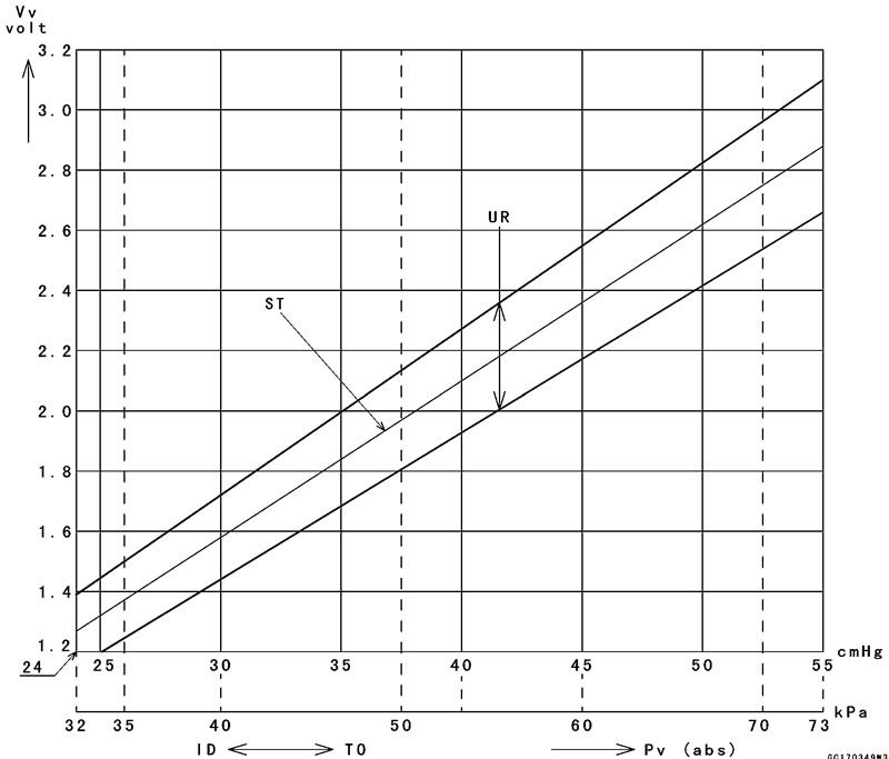
Check the output voltage, using the following formula and chart.
Suppose:
- Pg: Vacuum Pressure (gauge) to Sensor
- Pl: Local Atmospheric Pressure (absolute) measured by a barometer
- Pv: Vacuum Pressure (absolute) to Sensor
- Vv: Sensor Output Voltage (V) then Pv = Pl - Pg
For example, suppose the following data is obtained:
- Pg = 8 cmHg (Vacuum gauge reading)
- Pl = 70 cmHg (Varometer reading)
- Vv = 3.2 V (Digital meter reading) then Pv = 70 - 8 = 62 cmHg (Abs.)
Plot this Pv (62 cmHg) at a point [1] on the chart and draw a vertical line through the point. Then, you can get the usable range [2] of the sensor output voltage.
Usable range = 3.04-3.49 V
Plot Vv (3.2 V) on the vertical line. → Point [3].
Results: In the chart, Vv is within the usable range and the sensor is normal. Pv = 24-55 cmHg
- Pv = 55-86 cmHg
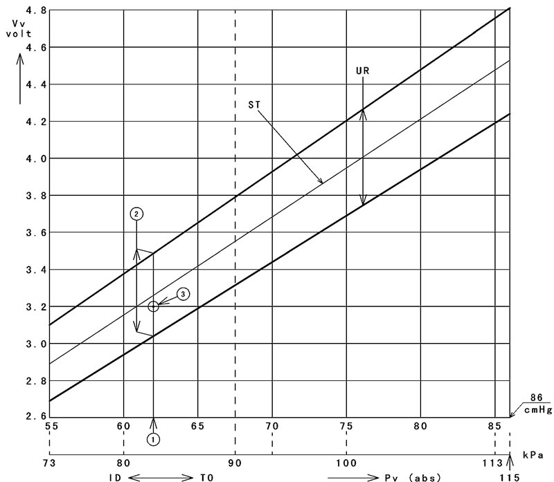
- ID: Idling
- Ps: Standard Atmospheric Pressure (Absolute)
- Pv: Throttle Vacuum Pressure (Absolute)
- ST: Standard of Sensor Output Voltage (V)
- TO: Throttle Full Open
- UR: Usable Range of Sensor Output Voltage (V)
- Vv: Inlet Air Pressure Sensor Output Voltage (V) (Digital Meter Reading)
Inlet Air Pressure Sensor Circuit
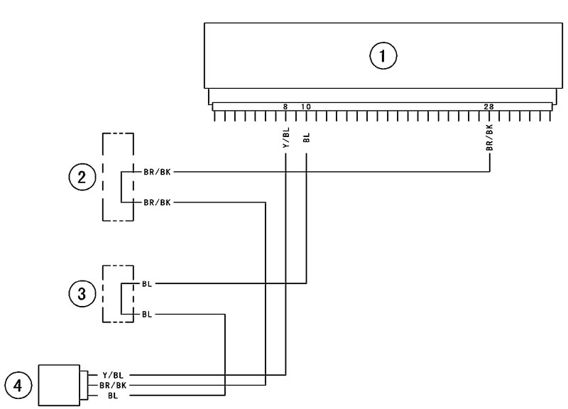
1. ECU; 2. Water-proof Joint E; 3. Water-proof Joint D; 4. Inlet Air Pressure Sensor
