
Removal
1. Remove the rider's seat (see page 16-13).
2. Disconnect the battery, negative (black) lead first.
3. Remove the fuel tank (see page 10-97).
4. Remove the airbox (see page 10-98).
5. Remove the throttle bodies (see page 10-107).
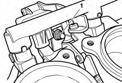
6. Remove the nut, metal washer and plastic washer attaching the idle control stepper arm to the idle speed control lever.
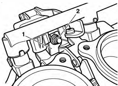
1. Idle speed control lever; 2. Nut etc.
7. Remove the two screws securing the idle speed control stepper motor to its bracket, then remove the stepper motor in the direction shown.
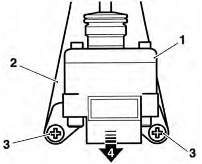
1. Idle speed control stepper motor; 2. Bracket; 3. Fixings; 4. Direction of removal
8. Leave the plastic collar and spring on the stepper motor arm.
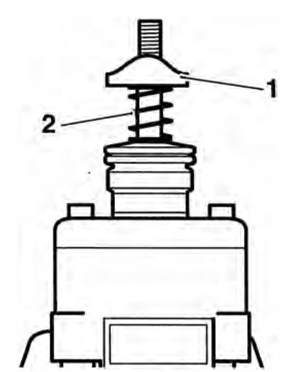
1. Collar; 2. Spring
Installation
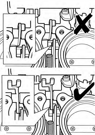
1. Ensure the Idle speed control lever is correctly positioned in relation to the throttle cam as shown below.
2. If removed, loosely fit the spring and collar on the stepper motor arm.
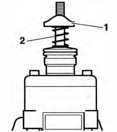
1. Collar; 2. Spring
3. Locate the stepper motor to its bracket and tighten the fixings to 3.5 Nm.
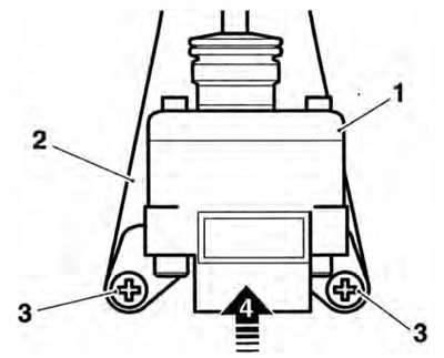
1. Idle speed control stepper motor; 2. Bracket; 3. Fixings; 4. Direction of fitting
4. Fit the plastic washer to the lever then fit the metal washer and nut.
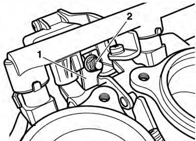
1. Idle speed control lever; 2. Nut etc.
5. Mount the throttle body onto the engine.
6. Temporarily reconnect the battery, positive (red) lead first.
7. Attach the Triumph diagnostic tool to the dedicated plug, refer to the Triumph Diagnostic Tool User Guide.
8. Turn the ignition to the 'ON' position.
9. On the diagnostic tool navigate to 'Engine Diagnostics' and select the 'Adjust Tune' button.
10. Select 'Idle Speed Control Stepper Renew' then press the 'Adjust' button.
11. On pressing the 'Adjust' key, the diagnostic tool will send a command that drives the throttle to the fully closed position. The tool will also display the voltage reading coming from the throttle position sensor which should be between the target voltage range of 0.58V and 0.62V.
Adjust Tune Procedure
Adjust the throttle position sensor as described in the service manual until the voltage reading is within the range shown below.
Press OK when the adjustment is complete.
Press cancel to cancel the adjustment process.
- Throttle Voltage: 0.59 V
- Target Voltage Range: 0.58-0.62 V
Adjusting parameter - Throttle Position Sensor Adjust
Adjust Tune Screen
12. Tighten the stepper arm nut on the idle speed stepper motor until a clearance of 0.5 mm can be measured between the idle speed control cam and the throttle roller.
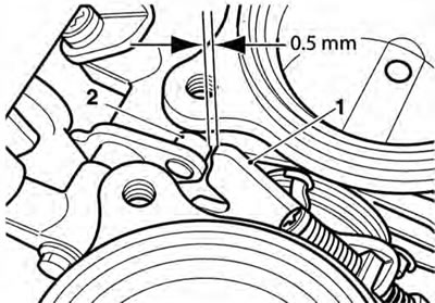
1. Idle speed control lever; 2. Throttle roller
13. Check the voltage reading shown on the software. If the reading is between the target voltage range, then proceed to step 17 If the reading is not within this range, adjustment must be made as described in steps 14 to 16.
14. Slacken the screws on the throttle position sensor.
15. Gently turn the throttle position sensor until the voltage reading shown on the software is between the target voltage range.
16. Tighten the sensor retaining screws to 2 Nm and recheck the voltage reading shown on the software. Repeat the adjustment if the reading is outside the specified range.
17. Click the 'OK' button to progress to the next adjustment.
Note: The diagnostic soware will calculate the target voltage range for when the throttle is in the fully open position.
18. On pressing the 'OK' button, the diagnostic tool will send a command that drives the throttle to the fully open position. The tool will also display the voltage reading coming from the throttle. position sensor which should be between the target voltage range calculated by the software and shown on the screen.
19. With the stepper fully opened, check the voltage shown on the software and, if necessary, adjust the nut on the top of the stepper arm until the software shows a voltage within the target voltage range shown on the screen. The reading on the screen will change from red to green, indicating that the reading is correct.
1. Adjustment nut
20. Click the 'OK' button to fully close the idle speed control stepper motor. After a minimum of 15 seconds (the tool will show 'Adapting' and not allow further actions to take place during this period), click the 'OK' button again to return the ECM to normal control.
Caution: Do not operate the throttle while the stepper motor is being adjusted, otherwise the incorrect value will be adapted and the engine will not start.
21. Turn the ignition to the 'OFF' position.
22. Disconnect the diagnostic tool.
23. Disconnect the battery, negative (black) lead first.
24. Check and adjust the throttle cable settings (see page 10-104).
Warning: Move the handlebars to left and right full lock while checking that the cables and harnesses do not bind. A cable or harness which binds will restrict the steering and may cause loss of control and an accident.
25. Refit the airbox (see page 10-101).
26. Refit the fuel tank (see page 10-92).
27. Reconnect the battery, positive (red) lead first.
28. Refit the rider's seat (see page 16-13).