
Removal
1. Remove the rider's seat (see page 16-13).
2. Disconnect the battery, negative (black) lead first.
3. Remove the fuel tank (see page 10-91).
4. Remove the airbox (see page 10-98).
5. Remove the throttle body assembly (see page 10-107).
6. Release the two screws and rotate the throttle position sensor clockwise through 45° to remove it from the left hand end of the throttle body. Collect the O-ring on disassembly.
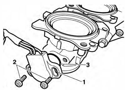
1. Throttle position sensor; 2. Screws; 3. O-ring
Installation
1. Fit the replacement throttle position sensor ensuring the O-ring is positioned correctly between the sensor and throttle body. Rotate the sensor through 45° anti-clockwise until the screw holes align.
2. Engage the new screws and washers supplied and part tighten such that the sensor can still be rotated.
3. Position the throttle body assembly near to its fitted position and reconnect the sensor and all other throttle body electrical connectors.
4. Reconnect the battery, positive (red) lead first.
5. Attach the Triumph diagnostic tool to the dedicated plug, refer to the Triumph Diagnostic Tool User Guide.
6. Turn the ignition to the 'ON' position.
7. On the diagnostic software navigate to and select the 'ADJUST TUNE' option.
8. At the next screen, select Throttle Position Sensor Adjust then click the 'Adjust' button.
9. On pressing the adjust button, the diagnostic tool will send a command, which drives the primary throttle to the fully closed position. The tool will also display the voltage reading coming from the throttle position sensor.
Adjust Tune Procedure
Adjust the throttle position sensor as described in the service manual until the voltage reading is within the range shown below Press OK when the adjustment is complete Press cancel to cancel the adjustment process.
- Throttle Voltage: 0.59 V
- Target Voltage Range: 0.58-0.62 V
Adjusting parameter - Throttle Position Sensor Adjust
Adjust Tune Screen
Gently rotate the new throttle position sensor until the voltage reading on the software shows 0.6 Volts +/- 0.02 Volts. The reading on the screen will turn green, indicating that the reading is correct.
Note: This is a setting voltage only. Because of the adaptive nature of the engine management system, the in-service voltage may vary from this setting figure.
10. Tighten the sensor retaining screws to 2 Nm and recheck the voltage reading shown on the tool. Repeat the adjustment if the reading is ouside the specified range.
11. Click on the OK button to return the throttle to normal control and return the diagnostic tool to the 'ADJUST TUNE' menu.
12. Disconnect the diagnostic tool.
13. Check that the throttle opens and closes without obstruction/sticking and has a smooth action throughout the full range of its movement. Rectify as necessary.
Warning: Operation of the motorcycle with an incorrectly adjusted throttle position sensor, or a throttle position sensor that causes the throttle to stick could result in loss of throttle control. Loss of throttle control could result in loss of control of the motorcycle and an accident.
Warning: Operation of the motorcycle with an incorrectly adjusted, incorrectly routed or damaged throttle cable could interfere with the operation of the brakes, clutch or the throttle itself. Any of these conditions could result in loss of control of the motorcycle and an accident.
14. Disconnect the battery, negative (black) lead first.
15. Refit the throttle body assembly (see page 10-107).
16. Refit the airbox (see page 10-101).
17. Refit the fuel tank (see page 10-92).
18. Reconnect the battery, positive (red) lead first.
19. Check and clear any stored faults using the diagnostic tool, refer to the Triumph Diagnostic Tool User Guide.
20. Refit the rider's seat (see page 16-13).