
Removal
Note: Because fuel stored in the fuel rail will be at 3 bar pressure, it is essential that the fuel pressure is reduced before any dismantling of the fuel rail takes place. To reduce pressure, briefly crank the engine with the fuel pump disconnected.
Warning: If the fuel rail is dismantled without first reducing pressure fuel may escape causing clothing and components to be coated with fuel. This would represent a serious fire hazard which could lead to burn injuries and damage to property.
1. Remove the rider's seat (see page 16-13).
2. Disconnect the battery, negative (black) lead first.
3. Remove the fuel tank (see page 10-91).
4. Remove the airbox (see page 10-98).
5. Disconnect the throttle position sensor multi-plug.
6. Disconnect the fuel injector multi-plugs.
7. Disconnect the idle speed control stepper motor multi-plug.
8. Release the clips securing the throttle bodies to the transition pieces.
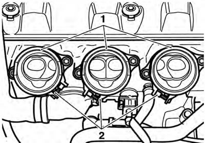
1. Transition piece (one per cylinder); 2. Clip location (throttle bodies removed for clarity)
9. Ease the throttle bodies from the transition pieces and lay the assembly carefully on the cam cover.
10. Release both throttle cables from the throttle cam (see page 10-105).
11. Remove the throttle bodies.
12. If required, release the screws securing the fuel rail to the throttle bodies.
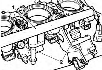
1. Fuel rail; 2. Fuel rail screws
13. Ease the fuel rail and injectors from the throttle bodies.
14. To detach the injectors from the fuel rail, gently ease the injector from the rail.
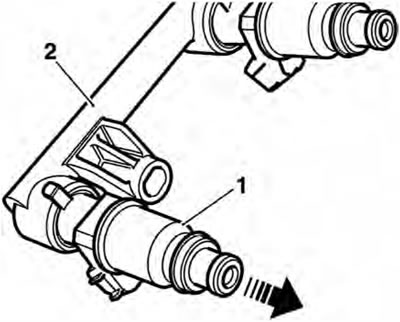
1. Injector; 2. Fuel rail
15. To detach the transition pieces from the head, release the screws, raise the transition pieces and collect the O-rings.
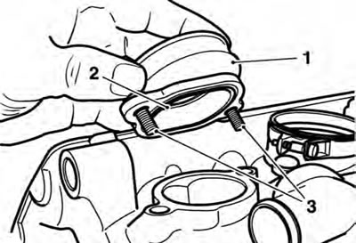
1. Transition piece; 2. O-ring; 3. Fixings
Inspection
1. Check all joints and seals for splits, cuts and damage.
2. Check the throttles for sticking, loose or damaged throttle plates.
3. Check the transition piece O-rings for damage.
Installation
1. Thoroughly clean the transition piece to cylinder head mating faces.
2. Refit the transition pieces to the head incorporating new O-rings to the joint face. Tighten the transition piece fixings to 12 Nm.
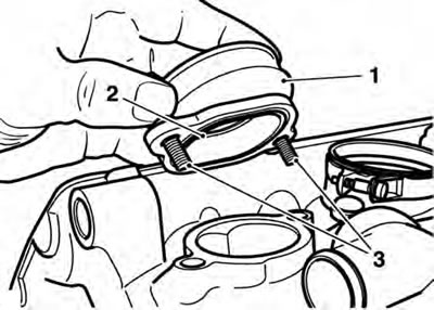
1. Transition piece; 2. O-ring; 3. Fixings
3. If the injectors have been removed from the fuel rail, refit them to the rail, ensuring the injector locating peg is fully engaged in the slot in the rail.
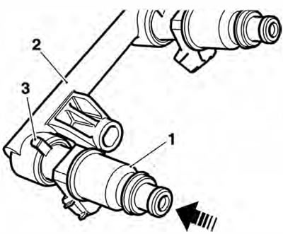
1. Injector; 2. Fuel rail; 3. Locating peg
4. Check the injector O-rings for splits and other damage. Replace as necessary.
5. Refit the injectors and fuel rail to the throttle bodies. Tighten the fuel rail screws to 3.5 Nm.
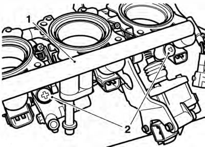
1. Fuel rail; 2. Fuel rail screws
6. Re-attach the throttle cables (see page 10-104).
Warning: The throttle body clips must be positioned as shown below. If the clips are not positioned as shown this could cause the throttle to stick, leading to loss of motorcycle control and an accident.
7. Refit the throttle bodies to the transition pieces and secure with the clips.
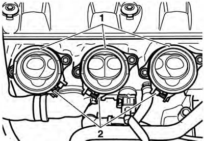
1. Transition piece (one per cylinder); 2. Clip location (throttle bodies removed for clarity)
8. Adjust the throttle cables (see page 10-104).
9. Reconnect the idle speed control stepper motor multi-plug.
10. Reconnect the fuel injector multi-plugs.
11. Reconnect the throttle position sensor multi-plug.
12. Refit the airbox (see page 10-107).
13. Refit the fuel tank (see page 10-92).
14. Reconnect the battery, positive (red) lead first.
15. Refit the rider's seat (see page 16-13).